Ford Parts Wiki | GM Parts Wiki
Home | Search | Browse | Marketplace | Messages | FAQ | Guest
|
Technical Service Manual January 1975 |
|
Prev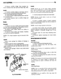
 Next
Next
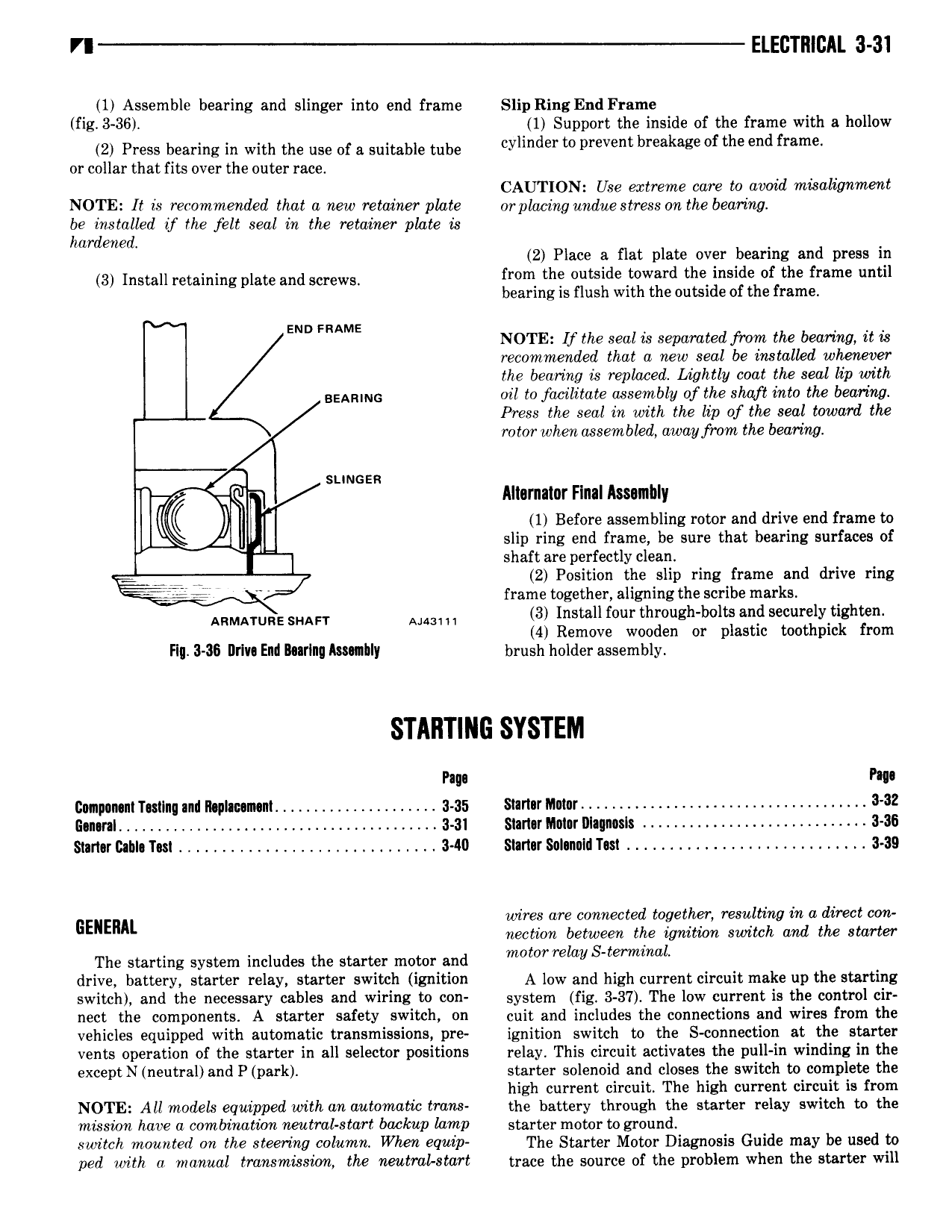
VI ELECTRICAL 3 31 I Assemble bearing and slinger into end frame Slip Ring End Frame fig 36 1 Support the inside of the frame with a hollow 2 Press bearing in with the use of a suitable tube cylmder W prevent breakam f the md frame or collar that fits over the outer race CAUTION Use extreme care to avoid misalilrnment NOTE It is recommended that a new retainer plate or placing undue stress on the bearing be installed U the felt seal in the retainer plate is hardened 2 Place a flat plate over bearing and press in 3 lnsmll retaining nlnm and Mrewn from the outside toward the inside of the frame until bearing is flush with the outside of the frame END FRAME NOTE If the seal is separated from the bearing it is recommended that a new seal be installed whenever the bearing is replaced Lightly coat the seal lip with eemamc oil to facilitate assembly of the shaft into the bearing Press the seal in with the lip of the seal toward the rotor when assembled away from the bearing I stances n Altamalur Flnal Assembly E I 1 Before assembling rotor and drive end frame to J ll slip ring end frame be sure that bearing surfaces of shaft are perfectly clean A ri r 2 Position the slip ring frame and drive ring ji frame together aligning the scribe marks ARMATURE SHAFT Mlm H 3 Install four through bolts and securely tighten 4 Remove wooden or plastic toothpick from Flu 3 36 Drlva End Imrlng Assably brush holder assembly STARTING SYSTEM Pagn Pm Ilumpamnl T sllnq and ll pl o m nl t t 3 35 Sltrlnr Mmnr 3 32 3 n raI t i tt 3 31 Slarlnr ltI l r lllaglnasls 3 36 Slamr I2abI Tosl 3 40 Slarlar Solanuld l sl t i 3 39 Gnnnnnl wires are connected together resulting in a direct con nection between the ignition switch and the starter The starting system includes the starter motor and motor relay S t rmmul drive battery starter relay starter switch ignition A low and high current circuit make up the starting switch and the necessary cables and wiring to con system fig 3 37 The low current is the control cir nect the components A starter safety switch on cuit and includes the connections and wires from the vehicles equipped with automatic transmissions pre ignition switch to the S connection at the starter vents operation of the starter in all selector positions relay This circuit activates the pull in winding in the exceptN neutral and P park starter solenoid and closes the switch to complete the high current circuit The high current circuit is from NOTE All models equipped with an automatic trans the battery through the starter relay switch to the mission have a combination neutral start backup lamp starter motor to ground switch mounted on the steering column When equip The Starter Motor Diagnosis Guide may be used to ped with a manual transmission the neutral start trace the source of the problem when the starter will