Ford Parts Wiki | GM Parts Wiki
Home | Search | Browse | Marketplace | Messages | FAQ | Guest
|
Technical Service Manual January 1975 |
|
Prev
 Next
Next
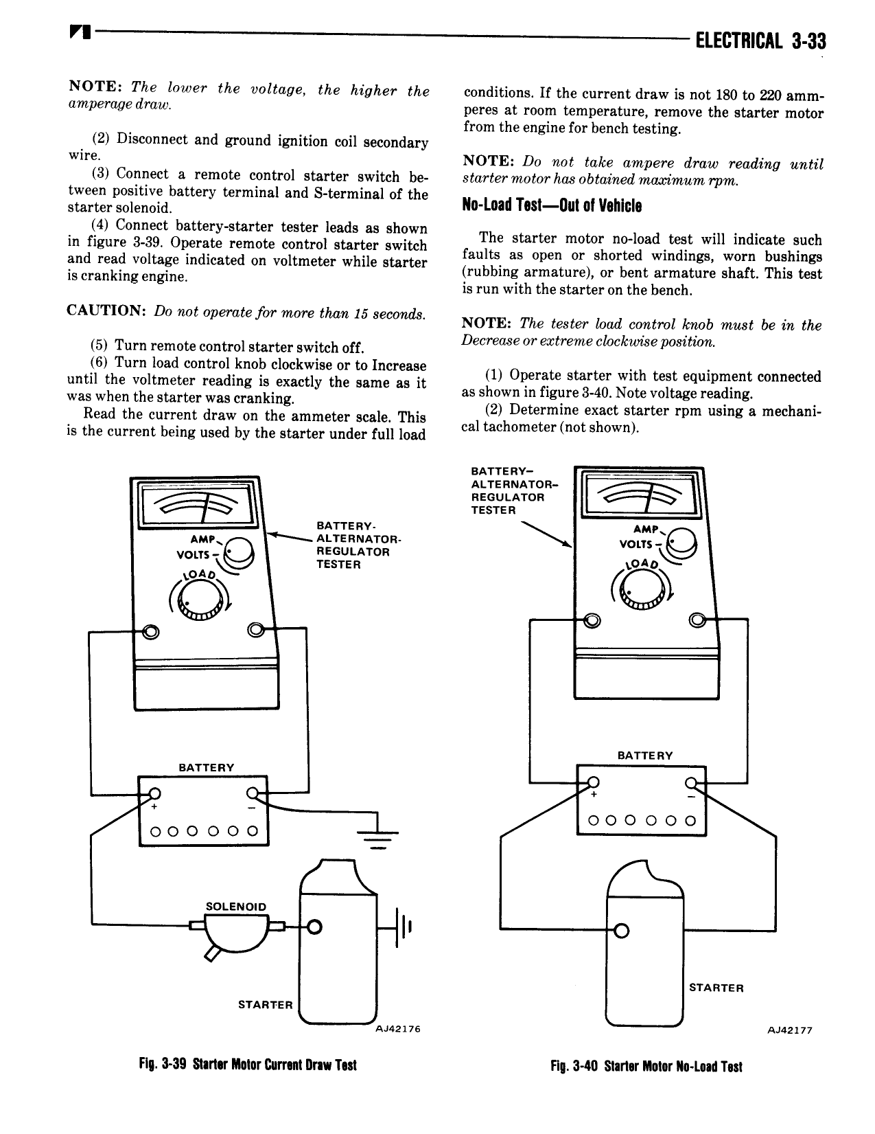
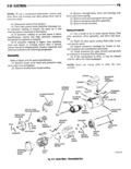
VI ELECTRICAL 3 33 NOTE The lower the voltage the higher the conditions If the current draw is not 180 to 220 amm amperuge draw peres at room temperature remove the starter motor from the engine for bench testing 2 Disconnect and ground ignition coil secondary wire NOTE Do not take ampere draw reading until 3 Connect e remote control starter switch be starter motor has obtained maximum mm tween positive battery terminal and S terminal of the starter wlmid lla Lnad Test Du nl Ilohlnla 4 Connect battery starter tester leads as shown The starter motor n0 0ad mst wm indium Such 2I f 2 3 Q 2 23 i v il 2 v lET SSE MS on or Storrs Wi Wm k g rubbing armature or bent armature shaft This test is Han mg Eng m is run with the starter on the bench AU N D0 mt oemrfw We mr 15 m NOTE The tester ma control me mm bein the k t 5 Turn remote control starter switch off Decrease mi extreme doc wwe pim um 6 Turn load control knob clockwise or to increase 1 Operate Starter with mst equipment connected until the voltmeter reading is exactly the same as it as shown in figure 340 Note voltage reading was when the Starter was cranking 2 Determine exact starter rpm using a mechani Read the current draw on the ammeter scale This cal mchometermot shown is the current being used by the starter under full load BATTERY f ALTERNATOR l TESTER BATTERY AMP AMR s ALrenuA ro vom REG vous Q TEs IE T L 4D tony Q 1 gg Q BATTE RV BATTERY r Q r 0 0 O 0 0 0 0 0 0 0 0 0 SOLENOID U I STARTER STARTER Mme 7 ng was sam mm Ilurnm umu rm Flu 340 S r1 r IMM M T