Ford Parts Wiki | GM Parts Wiki
Home | Search | Browse | Marketplace | Messages | FAQ | Guest
|
Technical Service Manual January 1975 |
|
Prev
 Next
Next
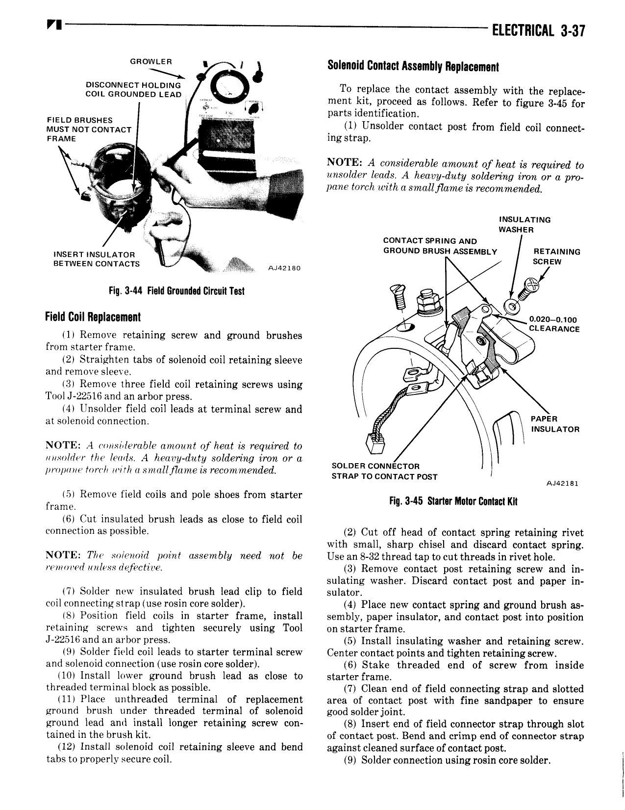
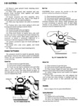
rl ELECTRICAL 3 37 GMWLER n 1 Selennid Contact Assembly Replacement gg RN JD LB gg To replace the contact assembly with the replace i l ment kit proceed as follows Refer to figure 3 45 for Q ywlgl parts identification HELD BRUSHES 1 Unsolder contact post from field coil connect Must not contact FRAME mg strap I NOTE A considerable amount of heat is required to K unsolder leads A heaoy duty soldering iron or a pro 2 K pane torch withasmdllflame is recommended 7 my l 2 J cumacr seams Ann l V GROUND ssusn AssEMsi v RETAINING imsznr msutaron savwssu comacrs I AMUB0 I 7 s Ew Flu 344 Field Grounded Clrcnlt Tm Field Ceil Replacement gi 2E ioo Auc 11 Remove retaining screw and ground brushes i 1 from starter frame E F 2 Straighten tabs of solenoid coil retaining sleeve I cw o Ole and remove sleex e 13 Remove three field coil retaining screws using Tool J 22516 and an arbor press vw 14 Unsolder field coil leads at terminal screw and All PAPER at solenoid connection INSULATOR NOTE 1 r isz lerabIe amount of heat is required to ulisolrliw the lemls A heavy duty soldering iron or a so R l pi opmu lorcll with a small flame is recommended 5 Tggr xiizgizmr ANNE 15 Remove field coils and pole shoes from starter nu 345 stm mm mmm Kn frame 16 Cut insulated brush leads as close to field coil connection as possible 2 Cut off head of contact spring retaining rivet with small sharp chisel and discard contact spring NOTE Tllo solenoid point assembly need not be Use an 8 32 thread tap tocut threads in rivet hole e mn e I unless detective 3 Remove contact post retaining screw and in sulating washer Discard contact post and paper in 17 Solder new insulated brush lead clip to field sulator coil connecting strap use rosin core solder 4 Place new contact spring and ground brush as 18 Position field coils in starter frame install sembly paper insulator and contact post into position retaining screws and tighten securely using Tool on starter frame J 22516 and an arbor press 5 Install insulating washer and retaining screw 19 Solder field coil leads to starter terminal screw Center contact points and tighten retaining screw and solenoid connection use rosin core solder 6 Stake threaded end of screw from inside 110 Install lower ground brush lead as close to starter frame threaded terminal block as possible 7 Clean end of field connecting strap and slotted 111 Place unthreaded terminal of replacement area of contact post with fine sandpaper to ensure ground brush under threaded terminal of solenoid good solderjoint ground lead aml install longer retaining screw con 8 Insert end of field connector strap through slot tained in the brush kit of contact post Bend and crimp end of connector strap 12 Install solenoid coil retaining sleeve and bend against cleaned surface of contact post tabs to properly secure coil 9 Solder connection using rosin core solder J I I