Ford Parts Wiki | GM Parts Wiki
Home | Search | Browse
|
Technical Service Manual January 1975 |
|
Prev

 Next
Next
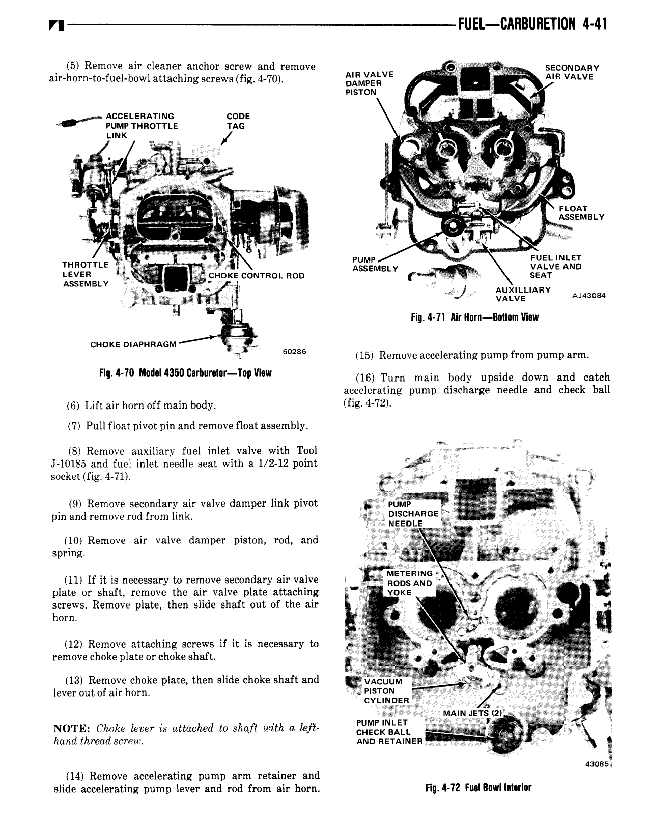
VI FUEL CAHBURETIUN 4 41 V 5 Remove air cleaner anchor screw and remove 9 ar W sscoumnv air horn t0 fuel bowl attaching screws fig 4 70 arm EQVE r J MR VALVE visrcn I M A Accztsnariuc cone L vumv mno r n z uc jr i V rmx A I gv tn t r ana L arm LT H V V t L v e V c 5 w glgl A B 2 7 V A 2 A sr A My 5 J 1 z W Me ZESQJELV j mer fg K V 9 s Q VL ez s VV e V mom M F 5g J r vatvz LEVER 41 cr mk conrrnoi Ron ASSEMBLY T SEAT ASSEMBLY ak c Auxirtianv A j VALVE aime Fig H1 Alr Hurn Bannm VI w ci ioxe niaennmm r 1 Emu 15 Remove accelerating pump from pump arm H 4 m M d N350 h r r T p VI 16 Turn main body upside down and catch accelerating pump discharge needle and check ball 6 Lift air horn off main body fig 4 72 7 Pull float pivot pin and remove float assembly 8 Remove auxiliary fuel inlet valve with Tool A ww J 10185 and fuel inlet needle seat with a 1 2 12 point V socket fig 4 71 LAW A p A Lg 3 19 Remove Secondary air valve damper link pivot Li Plf g X V pin and remove rod from link A g R E V 10 Remove air valve damper piston rod and Ir L ir 4 I l spring mb A w A L 11 If it is necessary to remove secondary air valve mgzgwxg W plate or shaft remove the air valve plate attaching T vcks I if screws Remove plate then slide shaft out of the air V f I A L horn V y J 4 or 12 Remove attaching screws if it is necessary to 1 u1 L L L remove choke plate or choke shaft E j V 2 gr fi g hc A y L tL V V N e A VL 2 wg 13 Remove choke plate then slide choke shaft and VACUUM L A A L lever out of air horn ER w F ii i R 1 NOTE Choke lever is attached to shaft with a Left CHECK BALL E s hand thread screw Ann neminen Q aussi 14 Remove accelerating pump arm retainer and slide accelerating pump lever and rod from air horn Flq 4 72 Fuallawllnhrlor

 Next
Next