Ford Parts Wiki | GM Parts Wiki
Home | Search | Browse
|
Technical Service Manual January 1975 |
|
Prev

 Next
Next
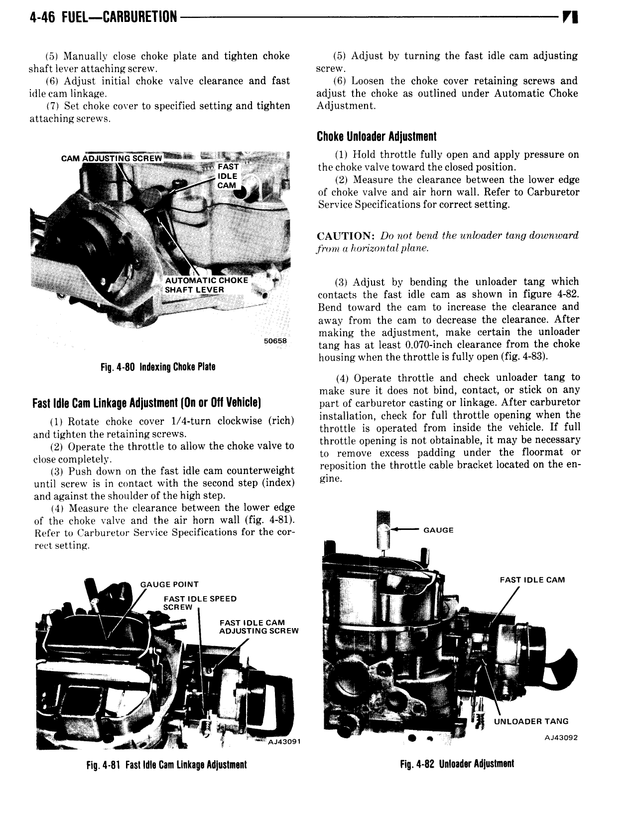
4 46 FUEL IIAIIBURETION 7 5 Manually close choke plate and tighten choke 5 Adjust by turning the fast idle cam adjusting shaft lever attaching screw screw 6 Adjust initial choke valve clearance and fast 6 Loosen the choke cover retaining screws and irlle cam linkage adjust the choke as outlined under Automatic Choke 7 Set choke cover to specified setting and tighten Adjustment attachingscrews Chaka Unlnadsr Alliuslmnnl GAM A DJUs NG GG Egvig 3 1 Hold throttle fully open and apply pressure on W V the choke valve toward the closed position tj 2 Measure the clearance between the lower edge 3 of choke valve and air horn wall Refer to Carburetor r G F Q 4 tw Service Specifications for correct setting i 3 t E j Y J A fe ii CAUTION Dv not bend the unloader tang downward G G gea jivmia 10riz0nI alplu rL r G a fj I G i Blgfd G j g KEt tl 3 Adjust by bending the unloader tang which 91 it contacts the fast idle cam as shown in figure 4 82 V V Bend toward the cam to increase the clearance and IG away from the cam to decrease the clearance After 50658 making the adjustment make certain the unloader tang has at least 0 070 inch clearance from the choke h h th th ttl fll f 4 83 nuG4G80 hmmm cmu Pm ousingw en e ro els u vopen ig 4 Operate throttle and check unloader tang to make sure it does not bind contact or stick on any FBS Idle Cllll LIIIKIQO MIIISIIMIII UII 0I U VOHIGIU part of carburetor casting or linkage After carburetor 1 Rotate choke cover 1 4 turn clockwise rich Smlla check for full jl tl p lWh ill gms and tighten the retaining Screws throttle is operated frogn msg e ve Qc e u 2 Operate the throttle to allow the choke valve to tl m Opemng ls nm Paula 6 lt may e necessary closecompletem to remove excess padding under the floormat or U3 Push down fm the fast idle cam Counterweight reposition the throttle cable bracket located on the en until screw is in contact with the second step index lime and against the shoulder of the high step I4 Measure the clearance between the lower edge of the choke valve and the air horn wall fig 4 81 Refer to Carburetor Service Specifications for the cor GAUGE rect setting i G GAUGE Pglm P i As r m e cAm V i msrnnte sreen scaaw G 2 G VM J l ibd1l i MEcc ew y V sr l l QN I Tala at G l L I v llol fl I I rlv l l kr fl I V l p rr jh 1 w x l i ge I 4 j yy l 7 3 X E um 0A sa YANG K G M 1 Ai43og1 I J Auzosz Hg Ml Fast I Cam Llnknqa Adlustnnnl Flg 4 82 lInInad r Arl uslm m

 Next
Next