Ford Parts Wiki | GM Parts Wiki
Home | Search | Browse
|
Technical Service Manual January 1975 |
|
Prev
 Next
Next
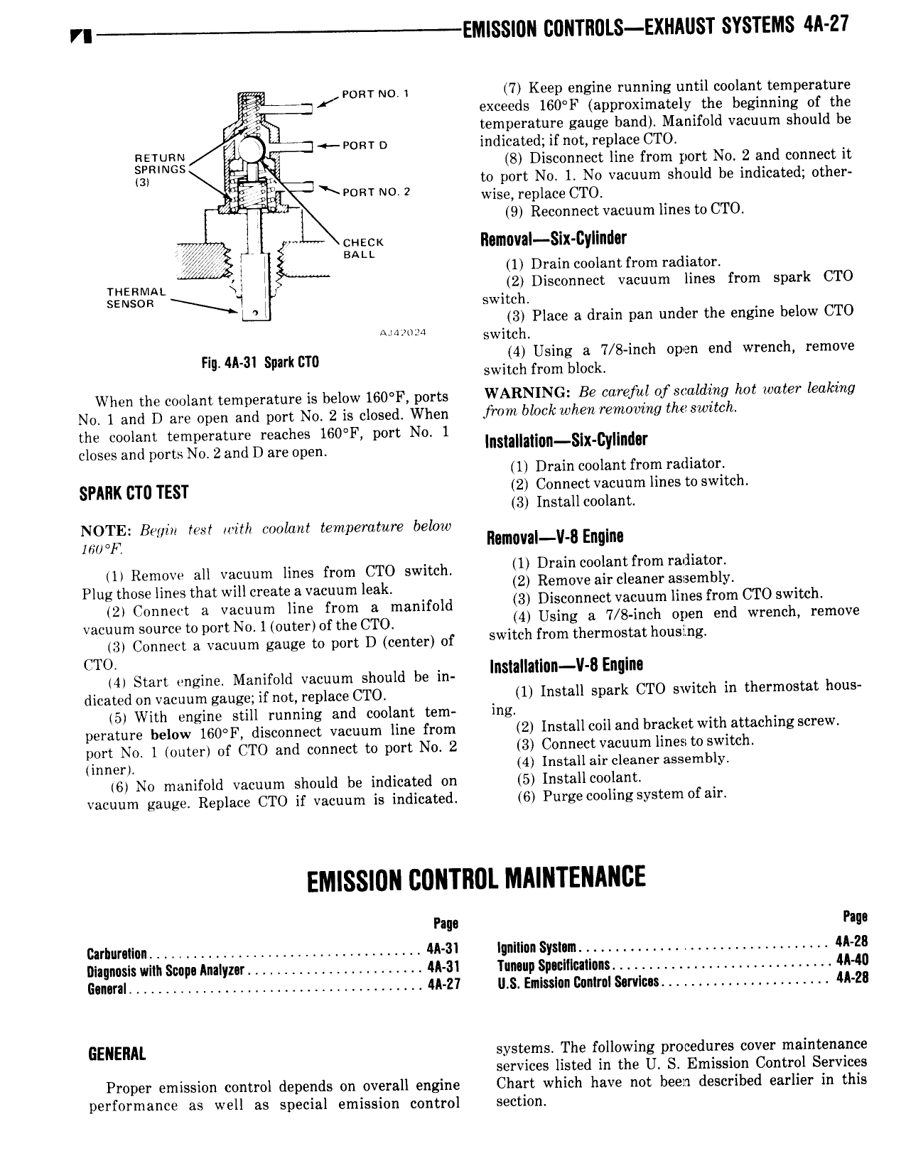
VI EMlSSI R lIONT l0LS EXHA ST SYSTEMS 4ll Z l I pom NO i 7 Keep engine running until coolant temperature exceeds 160 F approximately the beginning of the temperature gauge band Manifold vacuum should be RETURN roar o indicated ifnot replace CTO SPRINGS Q 8 Disconnect line from port No 2 and connect it 3i 1 t to port No 1 No vacuum should be indicated other PORT 2 wise replace CTO L 9 ReconnectvacuumlinestoCTO h V x wack Ilomoval Six Cylinilar wr 1 Drain coolant from radiator THERMAL Qi 2 Disconnect vacuum lines from spark CTO SENSGR switch G A 4 3 Place a drain pan under the engine below CTO 2 switch F Aka mc 4 Using a 7 8 inch open end wrench remove In spa T0 switch from block When the coolant temperature is below 1G0 F ports WARNING Be careful of scaliitng hot water leaking No 1 and D are open and port No 2 is closed When from block when removmg the swztch the coolant temperature reaches 160 F port No 1 closes and ports No 2 and D are open l smm n Slx cYl nd r 1 Drain coolant from radiator SPARK CTU TEST 2 Connect vacuum lines to switch 3 Install coolant NOTE Begin tos with coolant temperature below MWF ilomoval V it Englno 1 Remove all vacuum lines from CTO switch 1 Dmin l f m a Plug those lines that will create a vacuum leak 2 R m v an deaner aflgembly 2 Connect 8 Vacuum line mm 3 manifold 3 Disconnect vacuum lines from CTO switch vacuum source to port No 1 outerrof the CTO 4 Usmg a 7 8 mh Y end Wmnchr remlwe 3 Connect a vacuum gauge to port D center of swlmh from the m Smt h sl g CTO 41 Start engine Manifold vacuum should be in nsmla n v 8 Enum dicated on vacuum gauge if not replace CTO 1 Install spark CTO switch in thermostat hous 5 With engine still running and coolant tem ing I perature below 160 F disconnect vacuum line from 2 Install coil and brscketwith attachmgscrew port No 1 outer of CTO and connect to port No 2 3 Connect vacuumlines to switch inner 4 Install air cleaner assembly 6 No manifold vacuum should be indicated on 5 Install coolant vacuum gauge Replace CTO if vacuum is indicated 6 Purgecoolingsystem ofair Pago Pago Carhurnlion IMI ignition Systnm AA 28 Diagnosis with Scopn Anaiyznr A 3i Taming Siuolllutions M40 Ganural 4A 27 U S Erntsslon Control Smlons 4A 2B GENERAL systems The following procedures cover maintenance services listed in the U S Emission Control Services Proper emission control depends on overall engine Chart which have not been described earlier in this performance as well as special emission control section