Ford Parts Wiki | GM Parts Wiki
Home | Search | Browse | Marketplace | Messages | FAQ | Guest
|
Technical Service Manual January 1975 |
|
Prev

 Next
Next
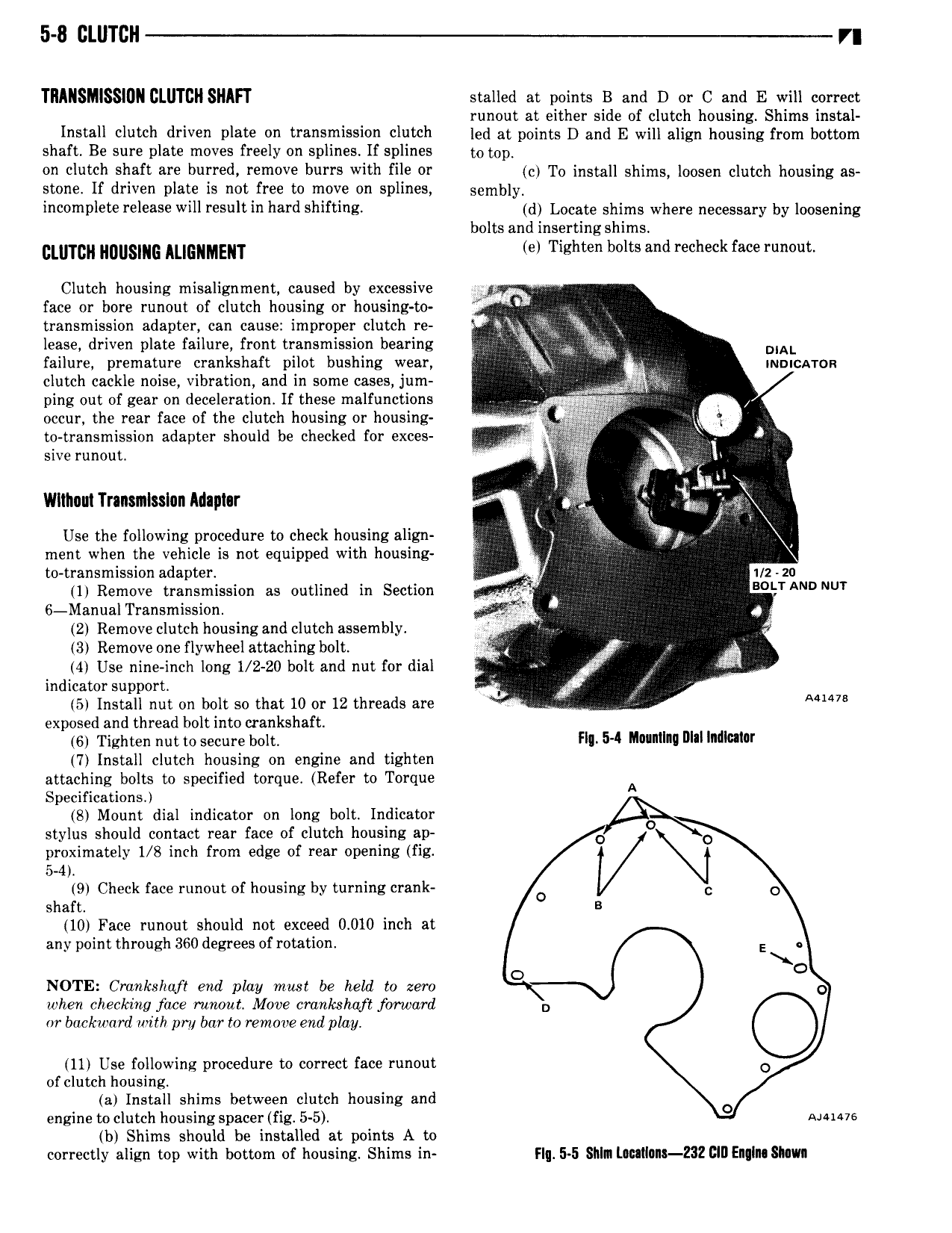
5 8 CLUTCH r TRMISMISSIDN CLUTCH SHIFT stalled at points B and D or C and E will correct runout at either side of clutch housin Shims instal Install clutch driven plate on transmission clutch led at points D and E will align nnuslig from bottom shaft Be sure plate moves freely on splines If splines to top on clutch shaft are burred remove burrs with file or C To install shin ls lonsen clutch housing ss stone If driven plate is not free to move on splines sembly incomplete release will result in hard shifting d Locate shims where necessary by loosening bolts and inserting shims glmcn NWSING ALIGNMENT e Tighten bolts and recheck face runout Clutch housing misalignment caused by excessive s face or bore runout of clutch housing or housing to r transmission adapter can cause improper clutch re ig fig lease driven plate failure front transmission bearing I g DIAL failure premature crankshaft pilot bushing wear QQ 5 x nnoicxrron clutch cackle noise vibration and in some cases jum ping out of gear on deceleration If these malfunctions H V occur the rear face of the clutch housing or housing I to transmission adapter should be checked for exces E sive runout Wlthnni Tranxmlsslnn Mapnr il Use the following procedure to check housing align g ment when the vehicle is not equipped with housing I to transmission adapter I I 2 20 1 Remove transmission as outlined in Section s mu AN NUT 6 Manual Transmission T 4 2 Remove clutch housing and clutch assembly V 3 Remove one flywheel attaching bolt ra V 4 Use nine inch long 1 2 20 bolt and nut for dial V l g indicator support 5 Install nut on bolt so that 10 or 12 threads are Mmm exposed and thread bolt into crankshaft 6 Tighten nut to secure bolt FII 5 Mvrnllnu Wl Inulwar 7 Install clutch housing on engine and tighten attaching bolts to specified torque Refer to Torque A Specifications S Mount dial indicator on long bolt Indicator stylus should contact rear face of clutch housing ap 0 O proximately 1 8 inch from edge of rear opening fig M N 5 4 9 Check face runout of housing by turning crank 0 D O shaft B 10 Face runout should not exceed 0 010 inch at any point through 360 degrees of rotation E O NOTE Crankshaft end play must be held to zero O 0 when checking face runout More crankshaft forward D or backward with pm bar to remove end play 11 Use following procedure to correct face runout O of clutch housing a Install shims between clutch housing and O engine to clutch housing spacer fig 5 5 Auius b Shims should be installed at points A to correctly align top with bottom of housing Shims in Flq 5 5 Sllln lI l llmt Z32 DEn In SMVII

 Next
Next