Ford Parts Wiki | GM Parts Wiki
Home | Search | Browse
|
Technical Service Manual January 1975 |
|
Prev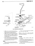
 Next
Next
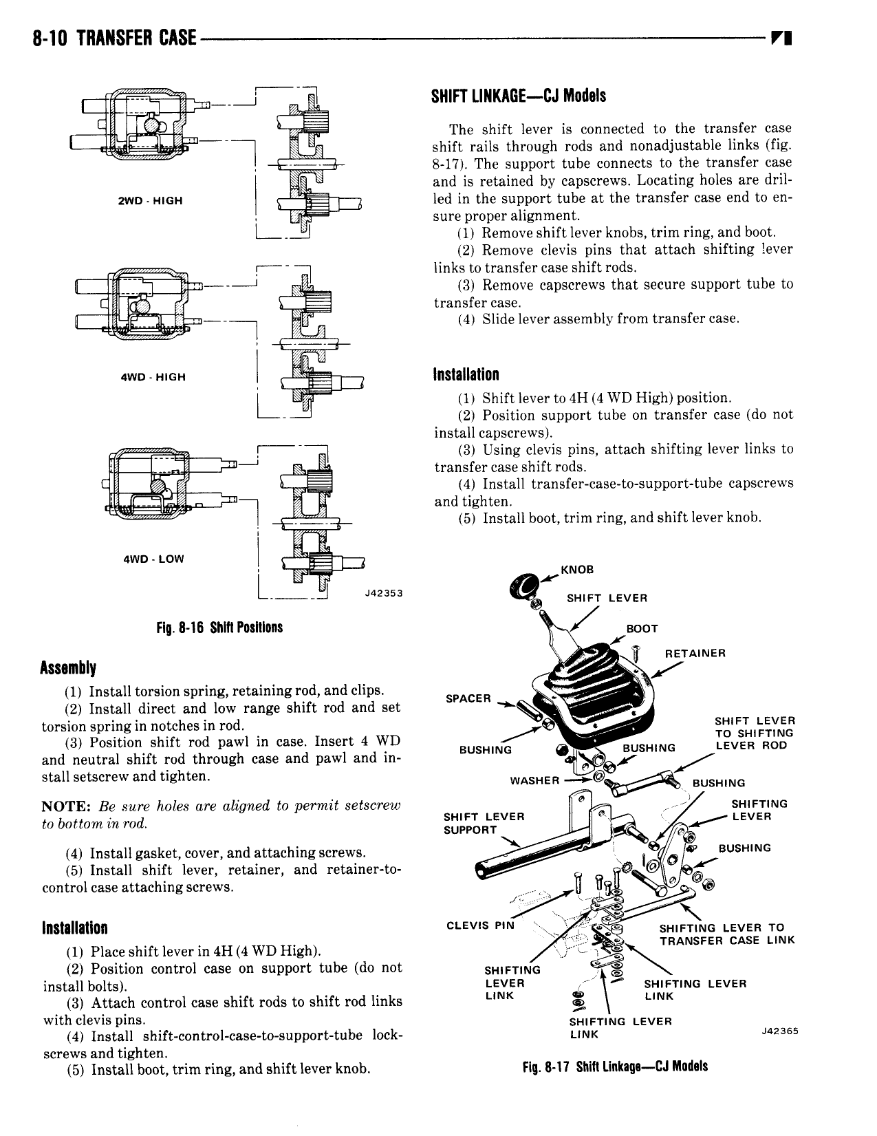
8 10 TRANSFER I r Q SHIFT LIRKAGE DJ Medals The shift lever is connected to the transfer case x shift rails through rods and nonadjustable links fig 8 17 The support tube connects to the transfer case and is retained by capscrews Locating holes are dril zwn mm 1 led in the support tube at the transfer case end to en W sure proper alignment l 1 Remove shift lever knobs trim ring and boot 2 Remove clevis pins that attach shifting lever 9 links to transfer case shift rods 3 Remove capscrews that secure support tube to I g transfer case lQ l l lT 4 Slide lever assembly from transfer case own nun l lnsllllillnn L 1 Shift lever to 4H 4 WD High position 2 Position support tube on transfer case do not install capscrews T Lmr g Elll Sg 1ls0E ns attach shifting lever links to 4 Install transfer case t0 support tube eapscrews and tighten 5 Install boot trim ring and shift lever knob 1 4wn Low l yi KNOB x J 5 s 1u r LEVER Flq 8 15 snm Potllluns I wm 1 neumeu Ammhly 1 Install torsion spring retaining rod and clips sucen 2 Install direct and low range shift rod and set torsion spring in notches in rod Q H LI Y 3 Position shift rod pawl in case Insert 4 VRD BUSHING ol BUSHING IQVER ROD and neutral shift rod through case and pawl and in l stall setscrew and tighten WASHER E RUSHING NOTE Be sure holes are aligned to perrnit setscrew K sn m 1 1NG to bottom in rod 3L L fVER B LEVER 4 Install gasket cover and attachingscrews l I O BU N 5 Install shift lever retainer and retainer to Q D 6 control case attaching screws V ll W L W V E UQ ka lnstallatlun L v S sH ET N LEVER To 1 Piece shift iever in 411 4 WD nigh E 2 Position control case on support tube do not gpm ING install bolts LEVER SHIFTING Leven 3 Attach control case shift rods to shift rod links K with clevis pins 4 SHIFHNG LEVER 4 Install sh1ft control case to support tube lock L1Nr 42365 screws and tighten 5 Install boot trim ring and shift lever knob Flu 8 1 I Shlli Llnkaqn CJ Rladals