Ford Parts Wiki | GM Parts Wiki
Home | Search | Browse
|
Technical Service Manual January 1975 |
|
Prev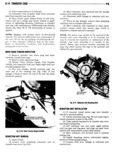
 Next
Next
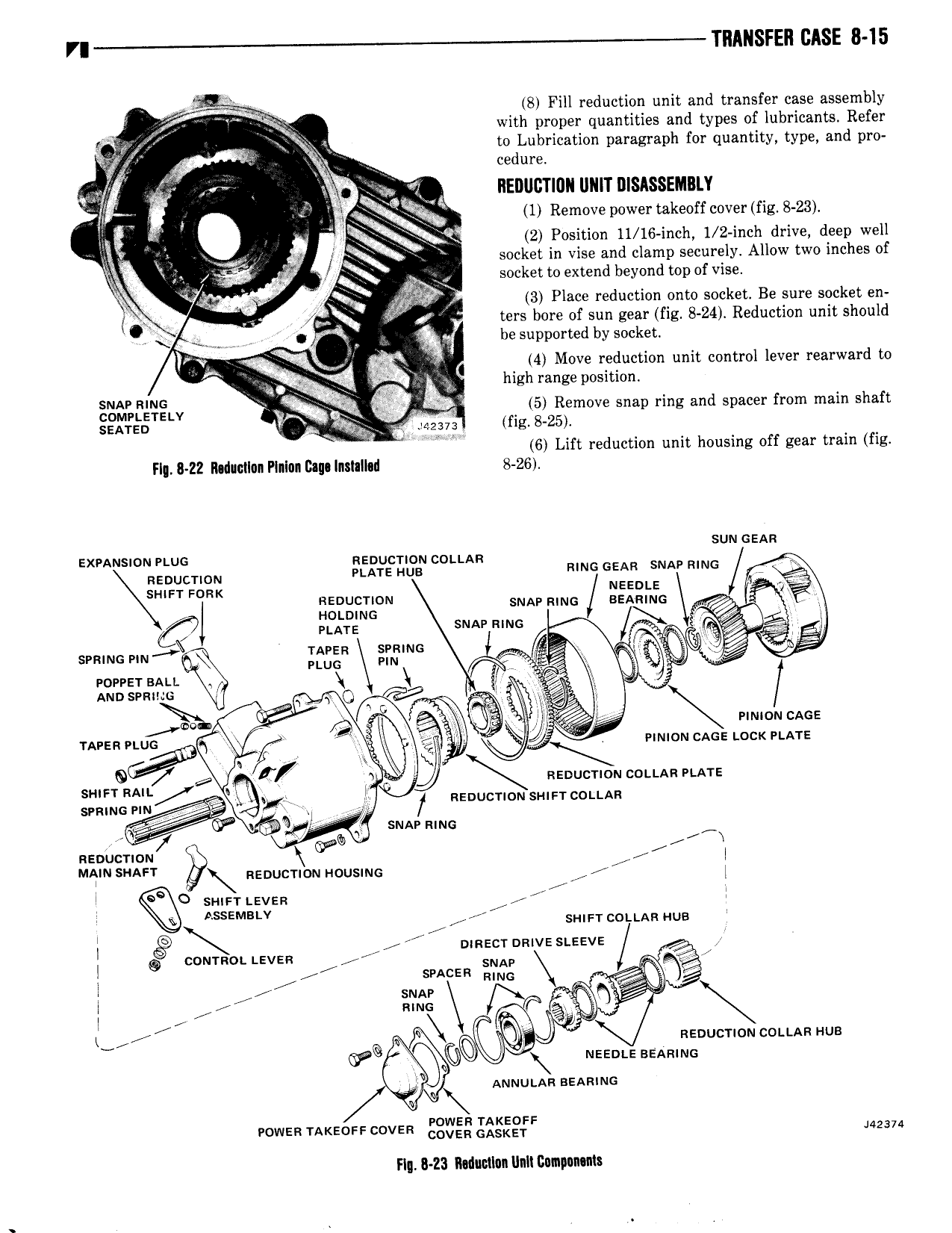
VI TRANSFER BASE 8 15 8 Fill reduction unit and transfer case assembly f with proper quantities and types of lubricants Refer 2 to Lubrication paragraph for quantity type and pro a Hfim V cedure yl w 3 i v T REDIIIZTIUN UNIT DISASSEIIBLY Q 1 Remove power takeoff cover fig 8 23 ax I Q 2 Position 11 16 inch 1 2 inch drive deep well lf V j socket in vise and clamp securely Allow two inches of g t r socket to extend beyond top of vise Z V Q V b 3 Place reduction onto socket Be sure socket en 4 ters bore of sun gear fig 8 24 Reduction unit should F9 V be supported by socket i Y il v 4 Move reduction unit control lever rearward to 1 high range position SNAP MMG M z2 5 Remove sna r d f h f P pk A p mg an spacer rom mam s a t SENTEETELV Y 4g my fig 8 25 W ki 6 Lift reduction unit housing off gear train fig FI 8 ZZ Ihdmlun Plnlnn Cm Inslalhd 8 26 sun cess Qf QT ON 5 2 315 me me sw me V sneer max ueeote y gig J 0N sm emo sesmuc K9 PLATE sun mms seams mu KSER f T e g Power ssu I 7 X ep Aunsvnxuo O VV rl oo V V V 1 mmc ucAce urea vtuc j mmou cme Locx une Q6 tp Y SH FT RAIL y s Renucnou co n An m A re SNLING PIN g f seoucnuu smer cou An V WW J SNAP uma neoucnou V i MA SW neoucnou nousmc i l sun 1 Leven 1 ASSEMBLY swan cottsn aus i G D V I S mecr mauve steeve Q cournow Leven 7 J l snces im i im l rr l i Y seuucrnou ccu u As n aus meente sesame Auuutss aesmuc rowen miceoee cover gglflvgg Q Eg F J42374 Fig 8 Z3 Mucllun InIl Cumpnnuns