Ford Parts Wiki | GM Parts Wiki
Home | Search | Browse
|
Technical Service Manual January 1975 |
|
Prev

 Next
Next
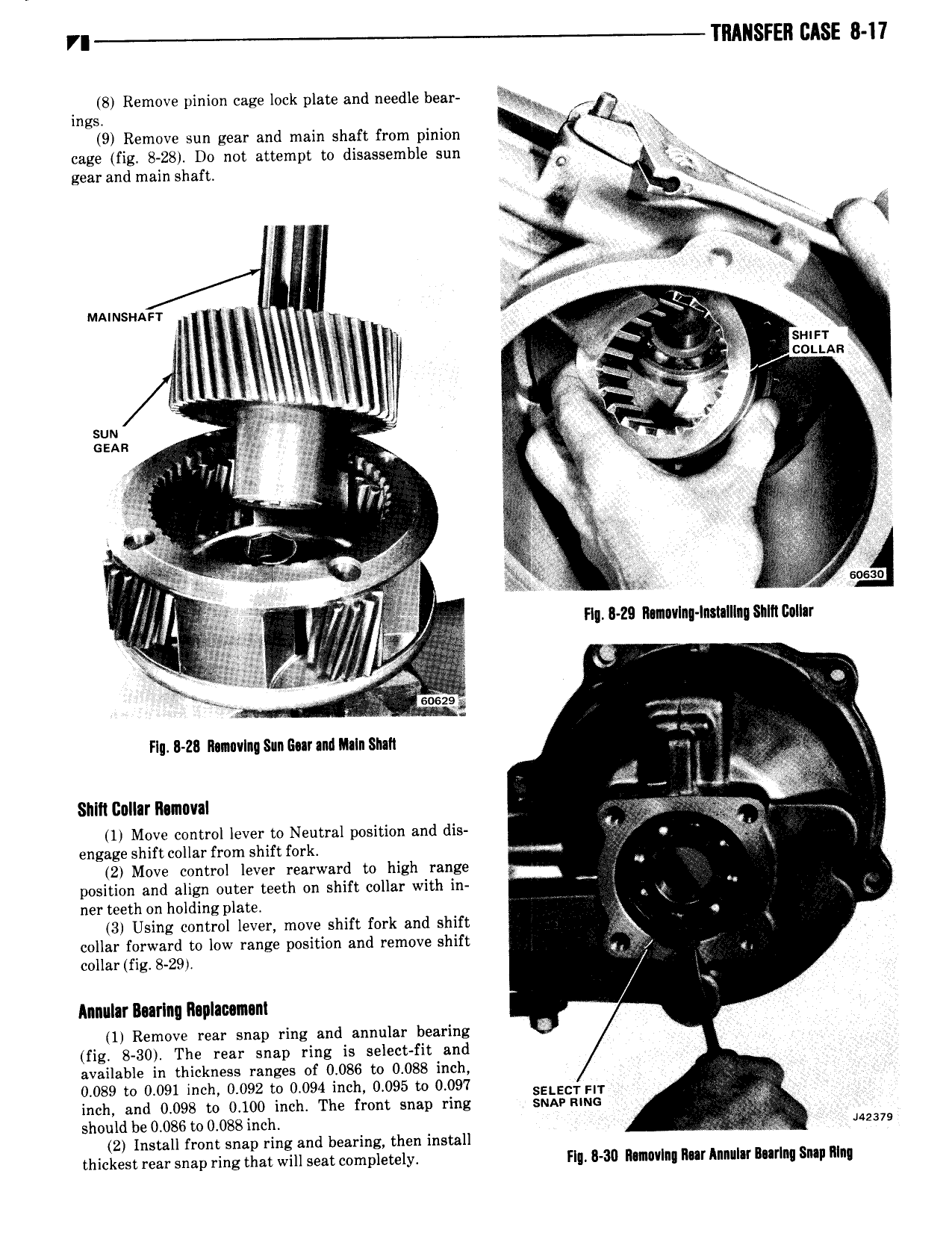
VI TRANSFER BASE 8 I7 8 Remove pinion cage lock plate and needle bear ings E 9 Remove sun gear and main shaft from pinion V cage fig 8 28 D0 not attempt to disassemble sun O jgx gear and main shaft 2 i Q j R R R i e 4 MAiMsi iAs r Q 1 Q I V Q A 1 I i V i i s ur r Ig aw gl aj c0i i An RR 5 so 5 E E 9 ER l YV Y E sun R can gif 2 g d 1 o Y X 6 J R A R 5 5 l M 4 R s M R RR Vg E I V wk g R 3 U Q x it 2 F R l w E l E gc E 1 ic i i 1 zi M i fa J j Q Mg Hg 29 R 1n vIn In t III SiIRGellar gx Z Q I l 53 f ah w ee 1 in il 2 W t 5 y Flu Z Ilsnnvlnqsnnlmrand Inalnsluh z R R V aa A a EEE Sl 1C0ll rR n0v l 1 Move control lever to Neutral position and dis engage shift collar from shift fork wm V 2 Move control lever rearward to high range position and align outer teeth on shift collar with in ner teeth on holding plate 3 Using control lever move shift fork and shift collar forward to low range position and remove shift E ig g collar fig 8 29 s Annular Burlnq Raplmmni 1 Remove rear snap ring and annular bearing 3 fig 8 30 The rear snap ring is select fit and available in thickness ranges of 0 086 to 0 088 inch 0 089 to 0 091 inch 0 092 to 0 094 inch 0 095 to 0 097 SELECT EI inch and 0 098 to 0 100 inch The front snap ring sun uiuc should be 0 086 to 0 088 inch uzsvs 2 Install front snap ring and bearing then install thickest rear snap ring that will seat completely FI R 30 RIm0v I Rilr Illlllf BIIIRIIQ Snap R n

 Next
Next