Ford Parts Wiki | GM Parts Wiki
Home | Search | Browse
|
Technical Service Manual January 1975 |
|
Prev
 Next
Next
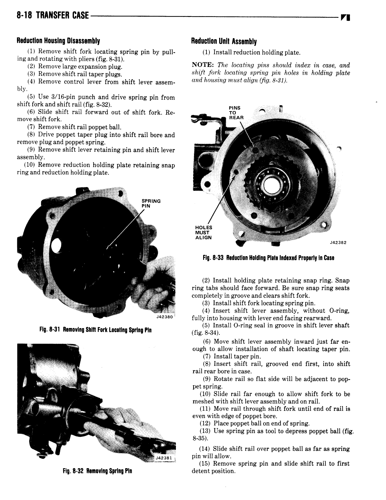
8 18 TRANSFER CASE r Raductlnn Rnuslng Rlsassambly Rcductlnn llnll Assembly 1 Remove shift fork locating spring pin by pull 1 Install reduction holding plate ing and rotating with pliers fig 8 3l V 2 Removelarge expansion plug NQTE The locotmg pms should mdeac wt case and 3 Remove Shift rainaperplugl shtft for locatmg sprang pm holes tn holdmg plate 4 Remove control lever from shift lever assem and hfmslng mmmllgll mg 8 91 bly 5 Use 3 16 pin punch end drive spring pin from shift fork and shift rail fig B 32 PINS q 6 Slide shift rail forward out of shift fork Re T0 A lf move shift fork REAR I 7 Remove shift rail poppet ball l 8 Drive poppet taper plug into shift rail bore and wm remove plug and poppet spring 9 Remove shift lever retaining pin and shift lever i w X assembly I lll W 10 Remove reduction holding plate retaining snap Ts It la ring and reduction holding plate nhl t l 5 i t og l 1 l i SPRING I i i i 4 k lj E Q we AZEB2 x g Flg 8 33 Rdumlun lloldlnu Plm Indmd Prnparly In Um ae ol 1 2 Install holding plate retaining snap ring Snap 4 32 1 Q 3 ring tabs should face forward Be sure snap ring seats is nh completely in groove and clears shift fork 0 ag ly 3 Install shift fork locating spring pin I 4 4 Insert shift lever assembly without 0 ring 2 fully into housing with lever end facing rearward H HH hmm nm Fart umlnl spun nn fl 3I11 stall O ring seal in groove in shift lever shaft 6 Move shift lever assembly inward just far en ough to allow installation of shaft locating taper pin 7 Install taper pin V A 8 Insert shift rail grooved end first into shift rail rear bore in case 9 9 Rotate rail so flat side will be adjacent to pop V 2 ii pet spring l 10 Slide rail far enough to allow shift fork to be 4 meshed with shift lever assembly and on rail 5 yi 4 11 Move rail through shift fork until end of rail is 4 s even with edge of poppet bore J 1 gag 12 Place poppet ball on end of spring D V 13 Use spring pin as tool to depress poppet ball fig VJ 5 i 8 35 X gm tv x 14 Slide shift rail over poppet ball as far as spring 423 pin will allow 4 V I V 15 Remove spring pm and slide shift rail to first Hg 32 MRIVIRI Sprlng Pla detent position