Ford Parts Wiki | GM Parts Wiki
Home | Search | Browse
|
Technical Service Manual January 1975 |
|
Prev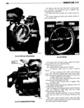
 Next
Next
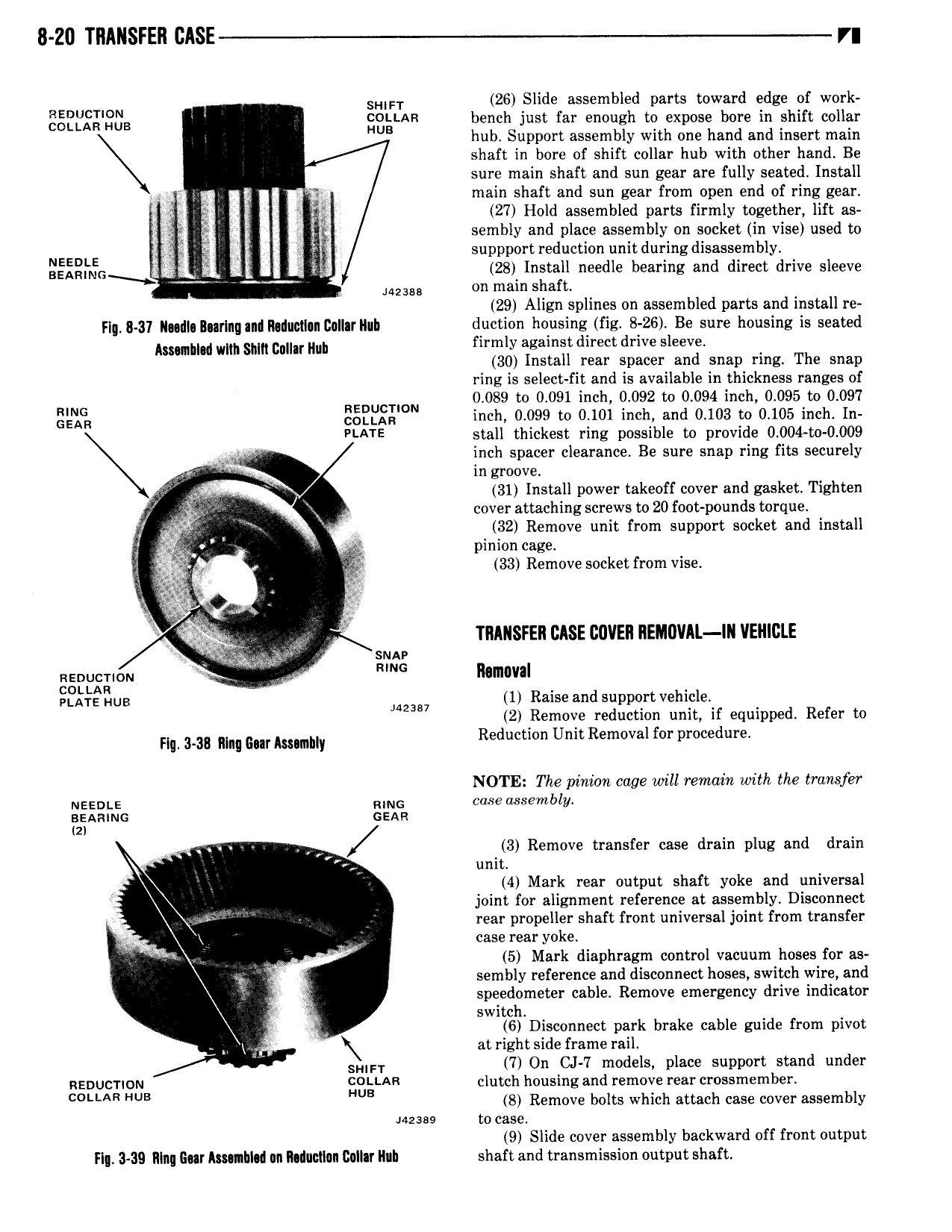
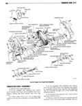
8 Z0 TRANSFER i r SHIFT 26 Slide assembled parts toward edge of work ggliigggi iiiis EDLLAR bench just far enough to expose bore in shift collar UB hub Support assembly with one hand and insert main shaft in bore of shift collar hub with other hand Be sure main shaft and sun gear are fully seated Install E ms main shaft and sun gear from open end of ring gear e I I 27 Hold assembled parts firmly together lift as V sembly and place assembly on socket in vise used to NEEDLE 5 I E suppport reduction unit during disassembly I FAFING T 28 Install needle bearing and direct drive sleeve IA238 on main shaft 29 Align splines on assembled parts and install re Flg 8 31 N dI During ani R iiuciI n Collar Rub duction housing fig 8 26 Be sure housing is seated ASWIINII INIIII sum cIIII I IIII firmly against direct drive sleeve 30 Install rear spacer and snap ring The snap ring is select fit and is available in thickness ranges of 0 089 to 0 091 inch 0 092 to 0 094 inch 0 095 to 0 097 ELPISII EEEBEEION inch 0 099 to 0 101 inch and 0 103 to 0 105 inch In PLATE stall thickest ring possible to provide 0 004 to 0 009 I inch spacer clearance Be sure snap ring fits securely I in groove Ja 31 Install power takeoff cover and gasket Tighten cover attaching screws to 20 foot pounds torque I g 2Y I 32 Remove unit from support socket and install V pinion cage t 5 33 Remove socket from vise R r I 3 i TRANSFER CASE COVER REIAUVAI IN VENNELE I sun nEnucr 0N H A mm MTWR Eigii lzug 1 Raise and support vehicle M2387 2 Remove reduction unit if equipped Refer to FII 3 3II RIIIII Gm MSIIIIIIII Reduction Unit Removal for procedure NOTE The pinion cage will remain with the transfer NEEDLE nine case assembly Iazeaaimc sean 3 Remove transfer case drain plug and drain unit 4 Mark rear output shaft yoke and universal I joint for alignment reference at assembly Disconnect rear propeller shaft front universal joint from transfer case rear yoke 5 Mark diaphragm control vacuum hoses for as sembly reference and disconnect hoses switch wire and speedometer cable Remove emergency drive indicator switch 6 Disconnect park brake cable guide from pivot at right side frame rail SHIFT 7 On CJ 7 models place support stand under REDUCTION coi i Aa clutch housing and remove rear crossmember L AR HUB HUB 8 Remove bolts which attach case cover assembly Jazass to case 9 Slide cover assembly backward off front output FI 3 39 Ring Eur Axmlblld un Rtilllltillln Blllllr Nlh shaft and transmission output shaft