Ford Parts Wiki | GM Parts Wiki
Home | Search | Browse
|
Technical Service Manual January 1975 |
|
Prev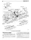
 Next
Next
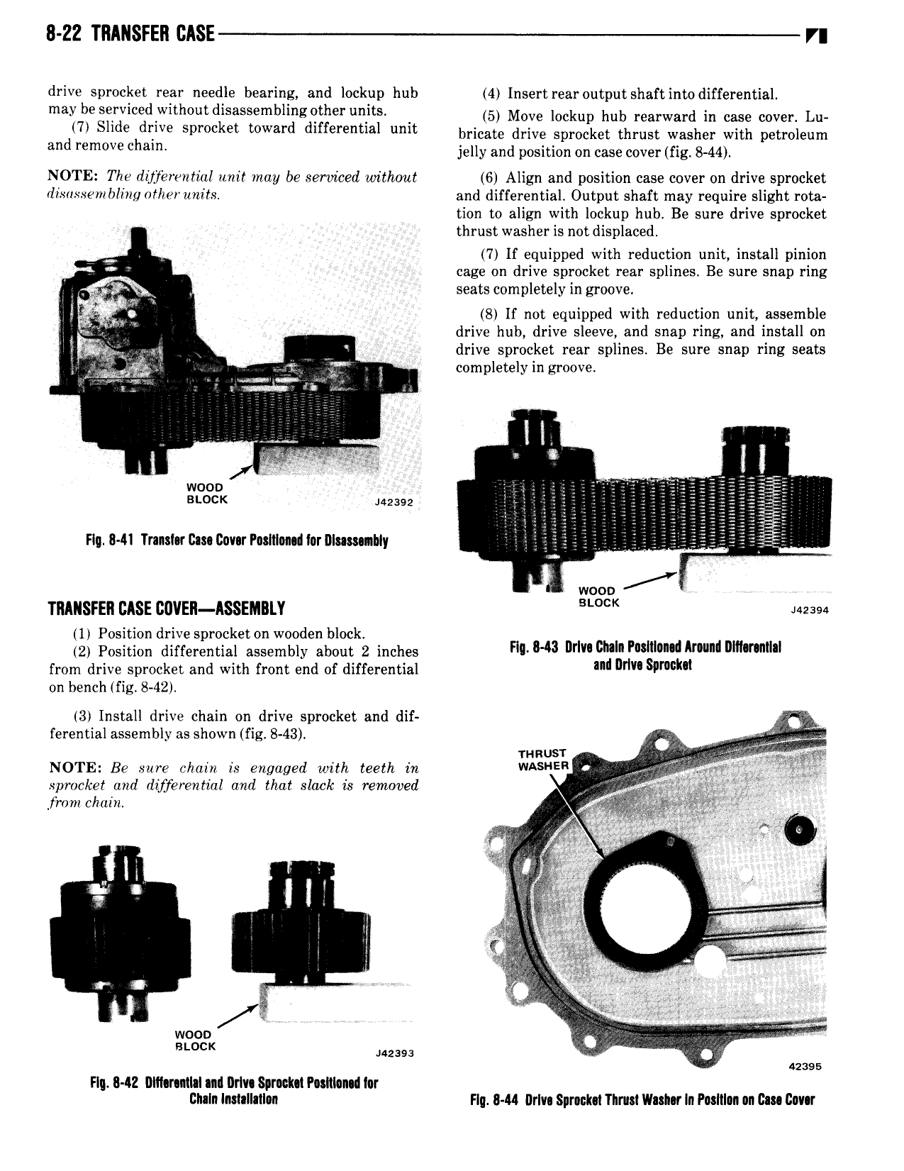
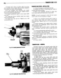
8 22 TRANSFER t r drive sprocket rear needle bearing and lockup hub 4 Insertrearoutput shaft intodifferential maT7b il ivl d Wlth ut d sassembllng wher u i S 5 Move lookup hub rearward in case cover Lu d 1 eh we sproc et toward dlffefenml limi bricate drive sprocket thrust washer with petroleum an remove C am jelly and position on case cover fig 8 44 NOTE The dzjjerwi tial unit may be serviced without 6 Align and position case cover on drive sprocket drsuxxemblhzg nfherunits and differential Output shaft may require slight rota tion to align with lockup hub Be sure drive sprocket thrust washer is not displaced 7 lf equipped with reduction unit install pinion cage on drive sprocket rear splines Be sure snap ring i2 P s seats completely in groove ip ESQ 8 lf not equipped with reduction unit assemble drive hub drive sleeve and snap ring and install on Eqg i A drive sprocket rear splines Be sure snap ring seats ug g f completely in groove l AT u u 1 l l wooo K 2392 ifi Fly R41 Tnnsl rI2a I2nv rPa ItInn l orDIu s nhIy Q V 3 E Z A wooo ZY TRIIISFEI BASE CUVEll ISSEMIl Y BWCK Must 1 Position drive sprocket on wooden block 2 Position differential assembly about 2 inches Fl 8 3 url ch P l l l mu nmmllml from drive sprocket and with front end of differential ml Dr Slmmm on bench fig 8 42 3 Install drive chain on drive sprocket and dii ferential assembly ns shown fig 8 43 mnusr X ge NOTE Be sure chain is engaged with teeth in WASNER f h sprocket and differential and that slack is removed I l L from chain z 1 w s a V ser It M 2 fw 5q c e g s M r 7 s J e P Ti Q Ls stock Mug O 42395 Flu R l2 Dlllarntlsi ml I rlv Sprnclm P sRl0n d lor Bhaln ImaIIalI n Flu 8 M Drlvs Spnukn Thrust Vlamr In P sItI n n Gm Ilmr