Ford Parts Wiki | GM Parts Wiki
Home | Search | Browse
|
Technical Service Manual January 1975 |
|
Prev

 Next
Next
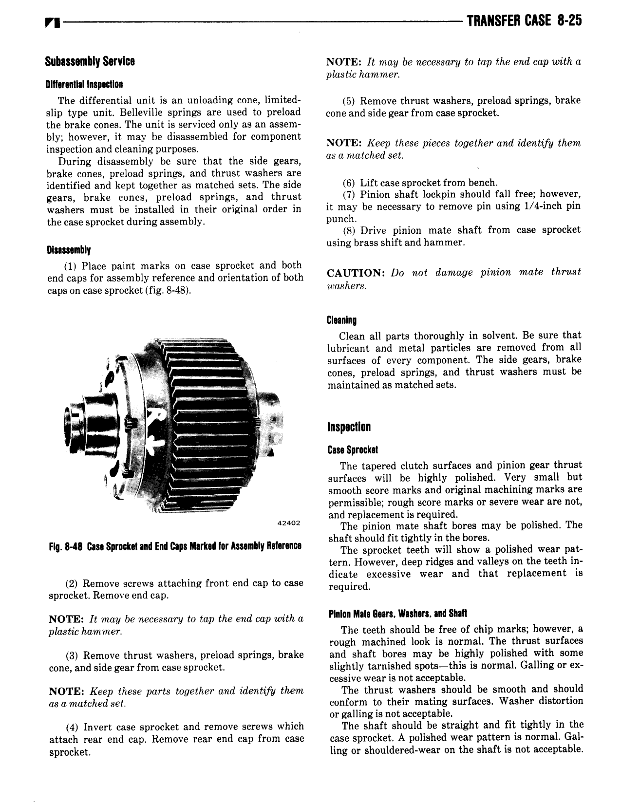
VI TRANSFER CASE 8 25 SIIIISRIIIIIY Sifllllib NOTE It may be necessary to tap the end cap with a last ha 4 nnnmman mptmn P W mm The differential l is Y l0adi E 001 llmlt d 5 Remove thrust washers preload springs brake slip type unit Belleville springs are used to preload com and side gem mm case spyockeg the brake cones4 The unit is serviced only as an assem bl h t bd bldf t 4 ingpec V d Lleggllg Surggifm Q or compcmm NOTE Keep these pieces together and identify them During disassembly be sure that the side gears asamumhed SEL brake cones preload springs and thrust washers are identified and kept together as matched sets4 The side 6 Lift 03 P 0 k t mm b mlhv gears brake cones preload springs and thrust 7 Pl i0 shaft lockpin should fall free ll0W V washers must be installed in their original order in if may be 5S Y to m0V Pm using 1 4 1 h Pm the case sprocket during assembly4 Punch 8 Drive pinion mate shaft from case sprocket mnumm using brass shift and hammer 1 Place paint marks on case sprocket and both end caps for assembly reference and orientation of both CAUTION D0 mt damage p mam thrust caps on case sprocket fig 8 48 w h 8 2I nIn r Clean all parts thoroughly in solvent4 Be sure that l r j lubricant and metal particles are removed from all i i i surfaces of every component The side gears brake cones preload springs and thrust washers must be 2 r a maintained as matched sets4 4 r e 6 g lnspocilnn fa ii F sg Gm Spruclm J Sl Z The tapered clutch surfaces and pinion gear thrust Q l xg surfaces will be highly polished Very small but 4 smooth soore marks and original machining marks are i permissible rough score marks or severe wear are not and replacement is required uic The pinion mate shaft bores may be polished The shaft should fit tightly in the bores Flq I4 C S rWk 1iIIdEMl DI NIark i Ihr kulltly R i f The sprocket teeth will show s polished wear pat tern However deep ridges and valleys on the teeth in dicate excessive wear and that replacement is 2 Remove screws attaching front end cap to we requgreg sprocket Remove end cap NOTE It may be necessary to tap the end cap with a mln Mm num wnmnt nd Shu plastic hammer The teeth should be free of chip marks however a rough machined look is normal The thrust surfaces 3 Remove thrust washers preload springs brake and shaft bores may be highly polished with some cone and side gear from case sprocket slightly tarnished spots this is normal Galling or ex cessive wear is not acceptable NOTE Keep these parts together and identify them The thrust washers should be smooth and should asamatched set conform to their mating surfaces Washer distortion or galling is not acceptable 4 Invert case sprocket and remove screws which The shaft should be straight and fit tightly in the attach rear end cap Remove rear end cap from case case sprocket A polished wear pattern is normal Gal sprocket ling or shouldered wear on the shaft is not acceptable

 Next
Next