Ford Parts Wiki | GM Parts Wiki
Home | Search | Browse
|
Technical Service Manual January 1975 |
|
Prev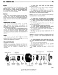
 Next
Next
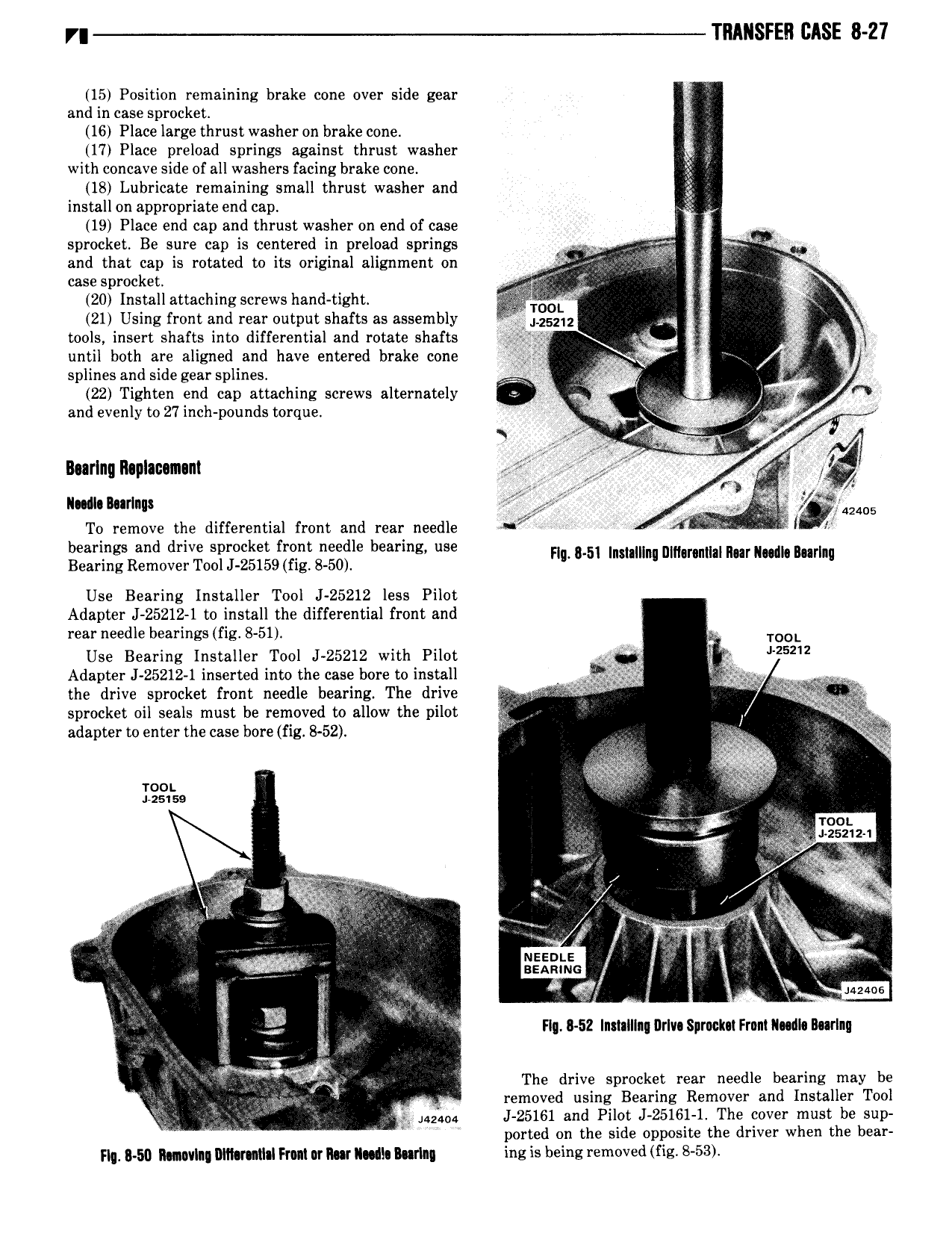
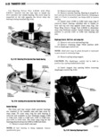
TRANSFER CASE 8 27 15 Position remaining brake cone over side gear A and in case sprocket 16 Place large thrust washer on brake cone 17 Place preload springs against thrust washer I with concave side of all washers facing brake cone 18 Lubricate remaining small thrust washer and install on appropriate end cap 19 Place end cap and thrust washer on end of case sprocket Be sure cap is centered in preload springs I f and that cap is rotated to its original alignment on I Y case sprocket r g j nr 20 Installattaching screws hand tight m L I 7 21 Using front and rear output shafts as assembly I i 25212 I tools insert shafts into differential and rotate shafts Q r ig T until both are aligned and have entered brake cone ri WQ e 4 splines and side gear splines I V 4 7 22 Tighten end cap attaching screws alternately pz l 4 I j and evenly to 27inch pounds torque M g I i A jr I I 5 During R plac m nt M fi 1 N Im MP 5 I l424 s To remove the differential front and rear needle f l r bearings and drive sprocket front needle bearing use FI 5I I I III nm II III r mdk Bu Bearing Remover Tool J 25I59 fig 8 50 l nu nl om ll Use Bearing Installer Tool J 25212 less Pilot Adapter J 25212 1 to install the differential front and rear needle bearings fig 8 51 E TOOL Use Bearing Installer Tool J 25212 with Pilot Wi 25212 Adapter J 25212 1 inserted into the case bore to install j 9 2 s A the drive sprocket front needle bearing The drive i T i 4 g 4 I sprocket oil seals must be removed to allow the pilot I f 2 adapter to enter the case bore fig 8 52 I I v iw if saw awe Y I Z P i v e yy I g wt e N V ig f I T II gx fr x k 2EE2h e i I I I ar I I l MMS S rs E H I r I SZ Inmlllng DrIv Sprnclm FrnnlIl dI Burlnu II i The drive sprocket rear needle bearing may be r il removed using Bearing Remover and Installer Tool V V iazapa J 25161 and Pilot J 25161 1 The cover must be sup ported on the side opposite the driver when the bear Flq 50 Ilmwlnn Mt v M I Fmt or Row I d Iurlm ing is being removed fig 8 53