Ford Parts Wiki | GM Parts Wiki
Home | Search | Browse
|
Technical Service Manual January 1975 |
|
Prev
 Next
Next
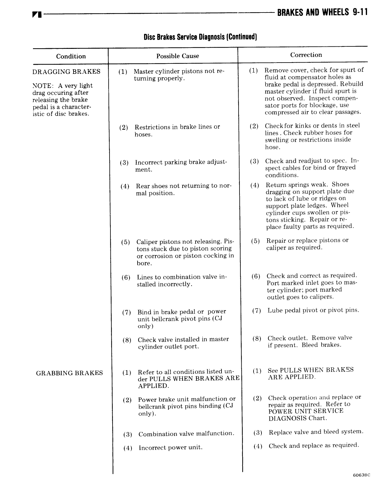
VI BRAKES AND WHEELS 9 11 Disc Brakes Sarvlu Dlagnnsis GanlInu d Condition Possible Cause Correction DRAGGING BRAKES 1 Master cylinder pistons not re 1 Remove cover check for spurt of g turning properly fluid at compensator holes as NOTE Alvery light brake pedal is depressed Rebuild drag occuring after master cylinder if fluid spurt is releasing the brake not observed Inspect compen pedal is a character sator ports for blockage use istic of disc brakes compressed air to clear passages 2 Restrictions in brake lines or 2 Checkfor kinks or dents in steel hoses lines Check rubber hoses for swelling or restrictions inside hose 3 Incorrect parking brake adjust 3 Check and readjust to spec In ment spect cables for bind or frayed conditions 4 Rear shoes not retuming to nor 4 Return springs weak Shoes mal position dragging on support plate due to lack of lube or ridges on support plate ledges Wheel cylinder cups swollen or pis tons sticking Repair or re place faulty parts as required 5 Caliper pistons not releasing Pis 5 Repair or replace pistons or tons stuck due to piston scoring caliper as required or corrosion or piston cooking in bore 6 Lines to combination valve in 6 Check and correct as required stalled incorrectly Port marked inlet goes to mas ter cylinder port marked outlet goes to calipers 7 Bind in brake pedal or power 7 Lube pedal pivot or pivot pins unit bellcrank pivot pins CJ only 8 Check valve installed in master 8 Check outlet Remove valve cylinder outlet port if present Bleed brakes GRABBING BRAKES 1 Refer to all conditions listed un 1 See PULLS WHEN BRAKES der PULLS WHEN BRAKES ARE ARE APPLIED APPLIED 2 Power brake unit malfunction or 2 Check operation and replace or bellcrank pivot pins binding CJ repair as required Refer to only POWER UNIT SERVICE DIAGNOSIS Chart 3 Combination valve malfunction 3 Replace valve and bleed system 4 Incorrect power unit 4 Check and replace as required