Ford Parts Wiki | GM Parts Wiki
Home | Search | Browse
|
Technical Service Manual January 1975 |
|
Prev
 Next
Next
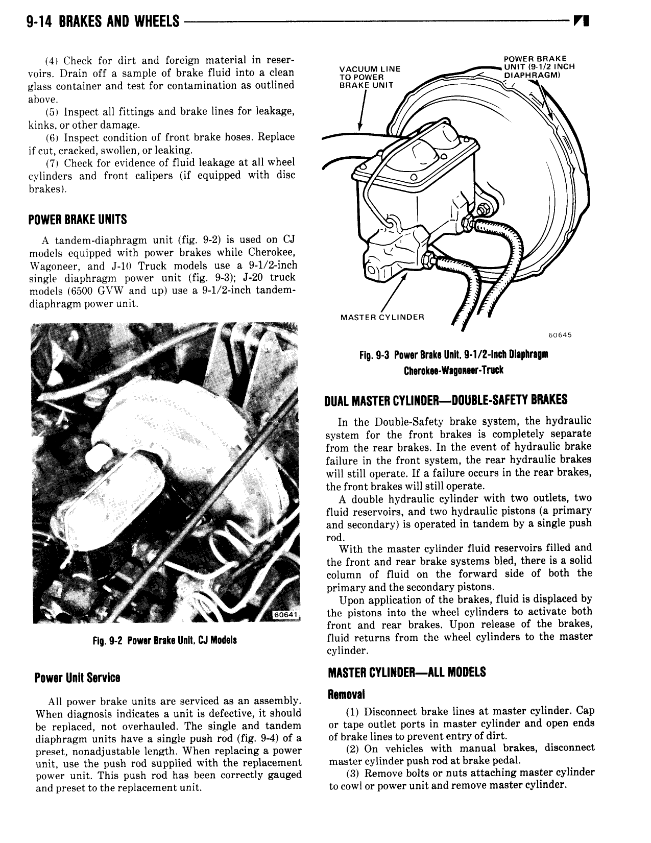
9 14 BRAKES ARB WHEELS r 44 Check for dirt and foreign material in reser Power snAl e voirs Drain off a sample of brake fluid into a clean 3 v E gm Lg J cH glass container and test for contamination as outlined BRAKE umr above 5 Inspect all fittings and brake lines for leakage kinks or other damage 6 Inspect condition of front brake hoses Replace if cut cracked swollen or leaking 7 Check for evidence of fluid leakage at all wheel 4 cylinders and front calipers if equipped with disc brakes POWER BRAKE UNITS Q A tandem diaphragm unit fig 9 2 is used on CJ models equipped with power brakes while Cherokee Wagoneer and J l Truck models use a 9 1 2 inch EF V single diaphragm power unit fig 9 3 J 20 truck models 6500 GVW and up use a 9 1 2 inch tandem diaphragm power unit V MAsrencvuNosn vv W t V i r g V X 60 5 6 F QQ r Flg 9 3 Pau rBnk Unll 9 I 2 lncI Dlaphmrn xr 4 Bn r k Vhq n r Tnuk te T di DUAL IAASTER l2YLIllI ER I 0UBLE SAFETY BRAKES Q f In the Double Safety brake system the hydraulic E V QJ system for the front brakes is completely separate V V from the rear brakes In the event of hydraulic brake 0 failure in the front system the rear hydraulic brakes V S j will still operate If a failure occurs in the rear brakes gf the front brakes will still operate i S A double hydraulic cylinder with two outlets two ff g I T Z fluid reservoirs and two hydraulic pistons a primary 1 if and secondary is operated in tandem by a single push v W rod i l With the master cylinder fluid reservoirs filled and 1 Q the front and rear brake systems bled there is a solid i l column of fluid on the forward side of both the a I primary and the secondary pistons h wi u SQ Upon application of the brakes fluid is displaced by soon the pistons mto the wheel cylinders to activate both front and rear brakes Upon release of the brakes H 9 z Pmnr lnkg n Mm fluid returns from the wheel cylinders to the master q l d cy m er pw um gown MASTER CYLINDER ALL HUBELS All power brake units are serviced as an assembly mmwal When diagnosis indicates a unit is defective it should 1 Disconnect brake lines at master cylinder Cap be replaced not overhauled The single and tandem or tape outlet ports in master cylinder and open ends diaphragm units have a single push rod fig 9 4 of a of brake lines toprevent entry of dirt preset nonadjustable length When replacing a power 2 On vehicles with manual brakes disconnect unit use the push rod supplied with the replacement master cylinder push rod at brake pedal power unit This push rod has been correctly gauged 3 Remove bolts or nuts attaching master cylinder and preset to the replacement unit to cowl or power unit and remove master cylinder