Ford Parts Wiki | GM Parts Wiki
Home | Search | Browse
|
Technical Service Manual January 1975 |
|
Prev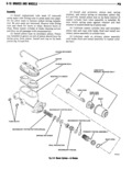
 Next
Next
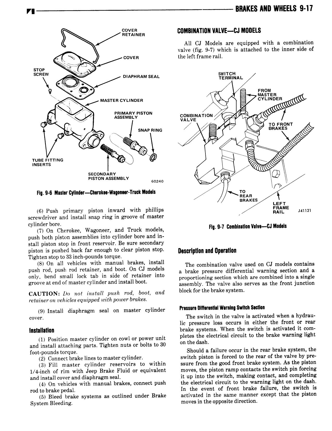
VI BRAKES MII WHEELS 9 I7 i F E 0M nnrnunvntvz c inun ts All CJ Models are equipped with a combination valve fig 9 7 which is attached to the inner side of K covan the left frame rail sro sca A RAMsEn I 5 o 9 mom B r umsrza cvunnen gilridirigen AZ s x s QJ Kgrgaglvvpnsrow SEEEENATION 0 l TO Fnowr sun mms Y w snakes s zi K r ir Q s wsa i m m s B 5 5 mszms I 4 os seem O Fl 9 6 Mult ll do CI k Vl Tr dxlmds Ilynr m an r u 1 E Rs s xs Leer 6 Push primary piston inward with phillips 52 5 Ulm screwdriver and install snap ring in groove of master cylinder bore 7 On Cherokee Wagoneer and Truck models HW B 1 cM Nm v I u malt push both piston assemblies into cylinder bore and in stall piston stop in front reservoir Be sure secondary piston is pushed back far enough to clear piston stop mscrlmlon and annual Tighten stop to 33 inch pounds torque Sag gn mh Vflxcgii lah azlgnsagt bgjikf XQTES The combination valve used on CJ models contains pu re p 0 ame 0 a brake pressure differential warning section and a only bend small lock tab in side of retainer into proportiomng section which are combined into a single groove at end of master cylmder and Install boot assembly The valve also serves as the front junction cauriom Do not muzi push md ami ma b1 kf r h br k v retainer on vehicles equipped with power brakes 9 Install diaphragm seal on master cylinder Pr M H r 1 lW l 8v h n 0V F The switch in the valve is activated when a hydrau lic pressure loss occurs in either the front or rear llltillllilllll brake systems When the switch is activated it com 1 position master cylinder on cowl or power unit pletes the electrical circuit to the brake warning light and install attaching parts Tighten nuts or bolts to 30 the dash foot pounds torque Should a failure occur in the rear brake system the 2 Connect brake lines to master cylinder switch piston is forced to the rear of the valve by pre 3 Fill master cylinder reservoirs to within ssure from the good front brake system As the piston 1 4 inch of rim with Jeep Brake Fluid or equivalent moves the piston ramp contacts the switch pin forcing and install cover and diaphragm seal it up into the switch making contact and completing 4 On vehicles with manual brakes connect push the electrical circuit to the warning light on the dash rod to brake pedal In the event of front brake failure the switch is 5 Bleed brake systems as outlined under Brake activated in the same manner except that the piston System Bleeding moves in the opposite direction