Ford Parts Wiki | GM Parts Wiki
Home | Search | Browse | Marketplace | Messages | FAQ | Guest
|
Technical Service Manual January 1975 |
|
Prev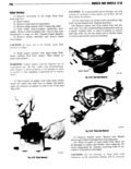
 Next
Next
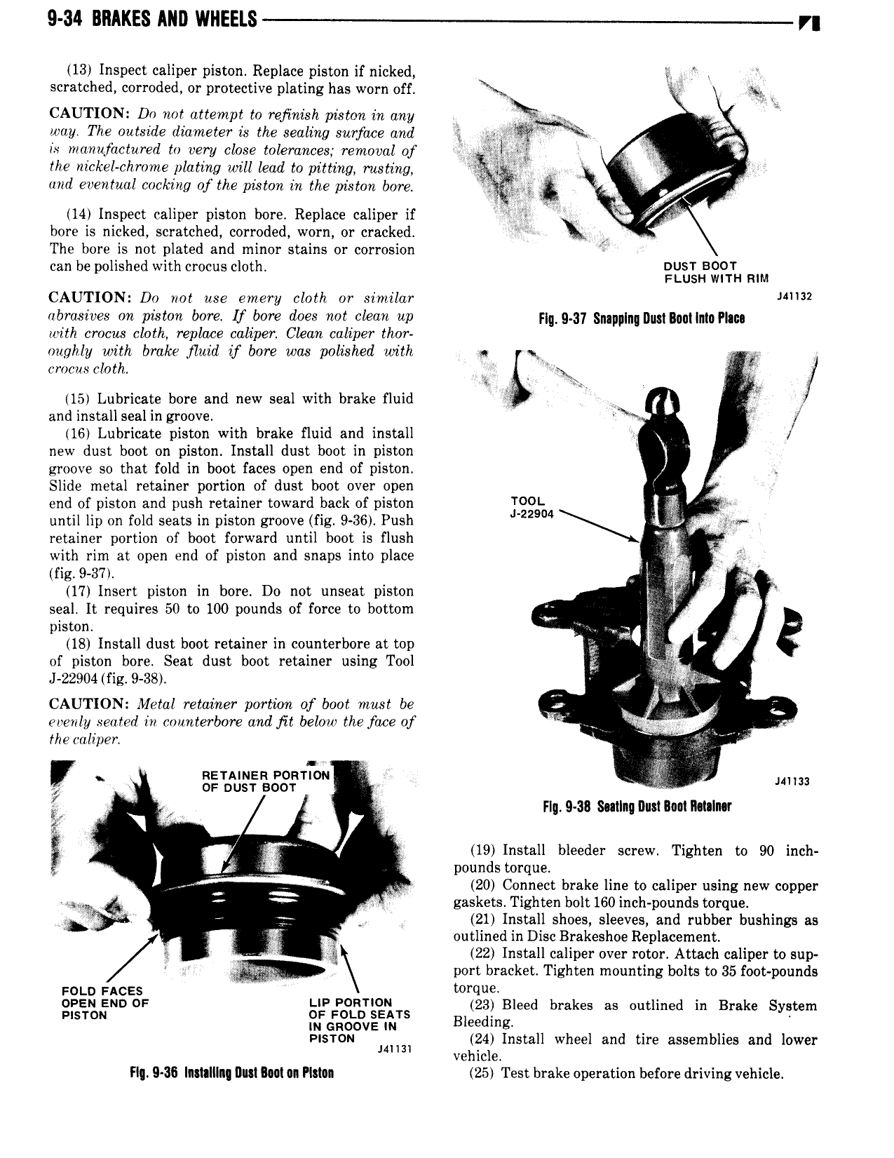
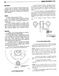
9 34 BRAKES AND WHEELS rg 13 Inspect caliper piston Replace piston if nicked g scratched corroded or protective plating has worn off Y CAUTION Do not attempt to rejinish piston in any Q way The outside diameter is the sealing surface and it is manufactured to very close tolerances removal of V the nickel chrome plating will lead to pitting rusting yi W 4 V and eventual cooking of the piston in the piston bore 14 Inspect caliper piston bore Replace caliper if i c V bore is nicked scratched corroded worn or cracked A V The bore is not plated and minor stains or corrosion i can be polished with crocus cloth IQEITQNBVQFTTH RIM CAUTION Do not use emery cloth or similar J 32 abrasives on piston bore If bore does not clean up F q g 31 n y pw m mg fhg with crocus cloth replace caliper Clean caliper thor oughly with brake fluid if bore was polished with ai x 1 crocus cloth 15 Lubricate bore and new seal with brake fluid V F and install seal in groove f 16 Lubricate piston with brake fluid and install ll new dust boot on piston Install dust boot in piston groove so that fold in boot faces open end of piston V Slide metal retainer portion of dust boot over open end of piston and push retainer toward back of piston YOUL l until lip on fold seats in piston groove fig 9 36 Push 22904 L retainer portion of boot forward until boot is flush with rim at open end of piston and snaps into place if Z mg 9 sv Q 17 Insert piston in bore Do not unseat piston V seal It requires 50 to 100 pounds of force to bottom piston Lx B 18 Install dust boot retainer in counterbore at top of piston bore Seat dust boot retainer using Tool J 22904 fig 9 38 j s CAUTION Metal retainer portion of boot must be 4 L evenly seated in counterbore and fit below the face of i theoaliper ij P lou I SE J 8 I y Flg 9 38 Sallnq Dusllncl I tnln r D E V 19 Install bleeder screw Tighten to 90 inch i pounds torque 20 Connect brake line to caliper using new copper M V gaskets Tighten bolt 160 inch pounds torque 21 Install shoes sleeves and rubber bushings as r outlined in Disc Brakeshoe Replacement p 22 Install caliper over rotor Attach caliper to sup port bracket Tighten mounting bolts to 35 foot pounds i 0 o FACES V OPEN END DF UP PORTWN 23 Bleed brakes as outlined in Brake System Pisrou 3 FGFF 3v E I TS Bleeding PISTON mm 1 Install wheel and tire assemblies and lower ve ic e Fl 9 36 ntlt lIIl Dlui IOM on HSAIII 25 Test brake operation before driving vehicle