Ford Parts Wiki | GM Parts Wiki
Home | Search | Browse | Marketplace | Messages | FAQ | Guest
|
Technical Service Manual January 1975 |
|
Prev
 Next
Next
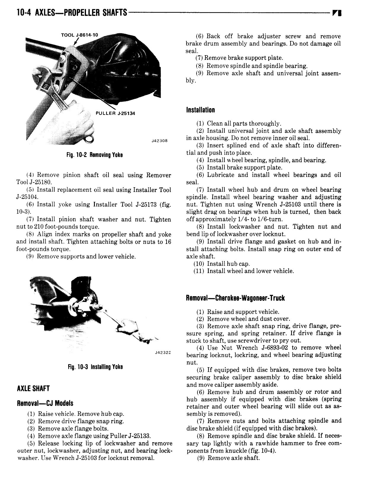
10 4 AXLES Pll0PELLER SHl FTS VI TOO 5 l 6 Back off brake adjuster screw and remove LL lyk brake drum assembly and bearings Do not damage oil 2 L V seal g I i 7 Remove brake support plate 1 355 8 Remove spindle and spindle bearing L il x 9 Remove axle shaft and universal joint assem 1 bly l L A J L FULLER LLLLLM Installallnn L 1 Clean all parts thoroughly i 2 Install universal joint and axle shaft assembly L J MMDB in axle housing Do not remove inner oil seal 3 Insert splined end of axle shaft into differen sig m z n ma v i i 1 L dIv ihl vii L L dl db L ns a w ee earing spin e an earing 5 Install brake support plate 4 Remove pinion shaft oil seal using Remover 6 Lubricate and install wheel bearings and oil Tool J 25180 seal 5 Install replacement oil seal using Installer Tool 7 Install wheel hub and drum on wheel bearing J 25104 spindle Install wheel bearing washer and adjusting 6 Install yoke using Installer Tool J 25173 fig nut Tighten nut using Wrench J 25103 until there is 10 3 slight drag on bearings when hub is turned then back 7 Install pinion shaft washer and nut Tighten offapproximately 1 4 to 1 6 turn nut to 210 foot pounds torque 8 Install lockwasher and nut Tighten nut and 8 Align index marks on propeller shaft and yoke bend lip of lockwasher over locknut and install shaft Tighten attaching bolts or nuts to 16 9 Install drive flange and gasket on hub and in foot pounds torque stall attaching bolts Install snap ring on outer end of 9 Remove supports and lower vehicle axle shaft 10 Install hub cap 11 Install wheel and lower vehicle U llamaval Dhuruku Wagnncar Truck L 1 Raiseand supportvehicle 2 Remove wheel and dust cover L l 3 Remove axle shaft snap ring drive flange pre ssure spring and spring retainer If drive flange is i stuck to shaft use screwdriver to pry out 4 Use Nut Wrench J 6893 02 to remove wheel J 232 bearing locknut lockring and wheel bearing adjusting nut H W 3 hmmm hk 5 If equipped with disc brakes remove two bolts securing brake caliper assembly to disc brake shield and move caliper assembly aside AXLE SHAFT 6 Remove hub and drum assembly or rotor and l f d h d b ak M 3 E T 3 5 E J5 1 1 Raise vehicle Remove hub cap sembly is removed 2 Remove drive flange snap ring 7 Remove nuts and bolts attaching spindle and 3 Remove axle flange bolts disc brake shield if equipped with disc brakes 4 Remove axle flange using PullerJ 25133 8 Remove spindle and disc brake shield If neces 5 Release locking lip of lockwasher and remove sary tap lightly with a rawhide hammer to free com outer nut lockwasher adjusting nut and bearing lock ponents from knuckle fig 10 4 washer Use Wrench J 25103 for locknut removal 9 Remove axle shaft