Ford Parts Wiki | GM Parts Wiki
Home | Search | Browse | Marketplace | Messages | FAQ | Guest
|
Technical Service Manual January 1975 |
|
Prev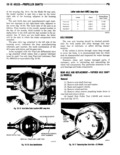
 Next
Next
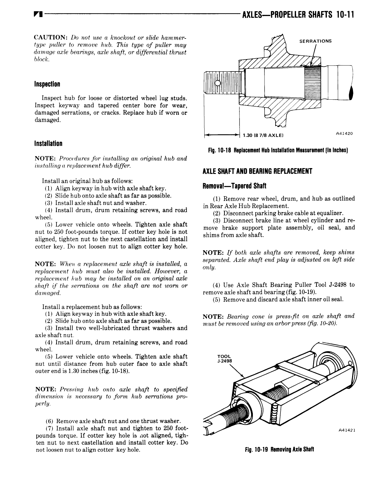
VI AXLES l l1l1l ELLER SHAFTS 10 11 CAUTION Do not use a knockout or slide hammer type puller to remove hub This type of puller may SERRATIONS damage ox e bearings uscle shaft or differential thrust V block l n E llllilllllllil gl Inspect hub for loose or distorted wheel lug studs Inspect keyway and tapered center bore for wear M damaged serrations or cracks Replace hub if worn or damaged 4 mo is 7 8 Axis 2 lnslallallan Flg I0 18 ll0pllo m n11lul1 Insnllatlon IlI asur n ln Inchu NOTE Pmcwdures for installing an original hub and installing ii replacement hub differ AXLE SNAFT AND BEARING REPLACEMENT Install an original hub as follows 1 Align keyway in hub with axle shaft key m Tall d shan 2 Slide hub onto axle shaft as faraspossible 1 Remove rear wheel drum and hub as Outlined 3 Install axle shaft nut and washer in Rear Axle Hub Replacergentl vh cy I dm drum i Mews md me 2 Disconnect parking bake ans at equaiimr W ee 3 Disconnect brake line at wheel cylinder and re 5 Lower vehicle onto wheels Tighten axle shaft move brake Su on late assembly Oil Seal and nut to 250 foot pounds torque If cotter key hole is not shims from axle Ssaft P aligned tighten nut to the next castellation and install cotter key Do not loosen nut to align cotter key hole If b h Le mf d k hl NOTE ot ax s ts are remove eep s ims NOTE When a replacement uscle shaft is installed a giigamted Axle Shaft md play is adjusted M Left Side repkzcement hub must also be instalkd Howeven a y replacement hub may be installed on an original axle sha if the serrations on the shaft are not warn or 4 USG Axl Shaft B 8 l 8 Puller T00l 2498 to damaged remove axle shaft and bearing fig 10 19 5 Remove and discard axle shaft inner oil seal Install a replacement hub as follows 1 Align keyway in hub with axle shaft key t I nd 2 Slide hub onto axle shaft as far as possible 23 gl 5 fmsgyljili f0 3yl a 3 Install two well lubricated thrust washers and V axle shaft nut 4 Install drum drum retaining screws and road wheel 5 Lower vehicle onto wheels Tighten axle shaft 100 v nut until distance from hub outer face to axle shaft J 249 f outer end is 1 30 inches fig 10 18 Q NOTE Pressing hub onto axle shaft w specified l dimension is necessary to form hub serrations pro S perly it E 6 Remove axle shaft nut and one thrust washer El 7 Install axle shaft nut and tighten to 250 foot N A 2 pounds torque If cotter key hole is not aligned tigh ten nut to next castellation and install cotter key Do not loosen nut to align cotter key hole Fly 10 19 RIIIIWIIII AXII Slllll