Ford Parts Wiki | GM Parts Wiki
Home | Search | Browse | Marketplace | Messages | FAQ | Guest
|
Technical Service Manual January 1975 |
|
Prev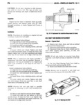
 Next
Next
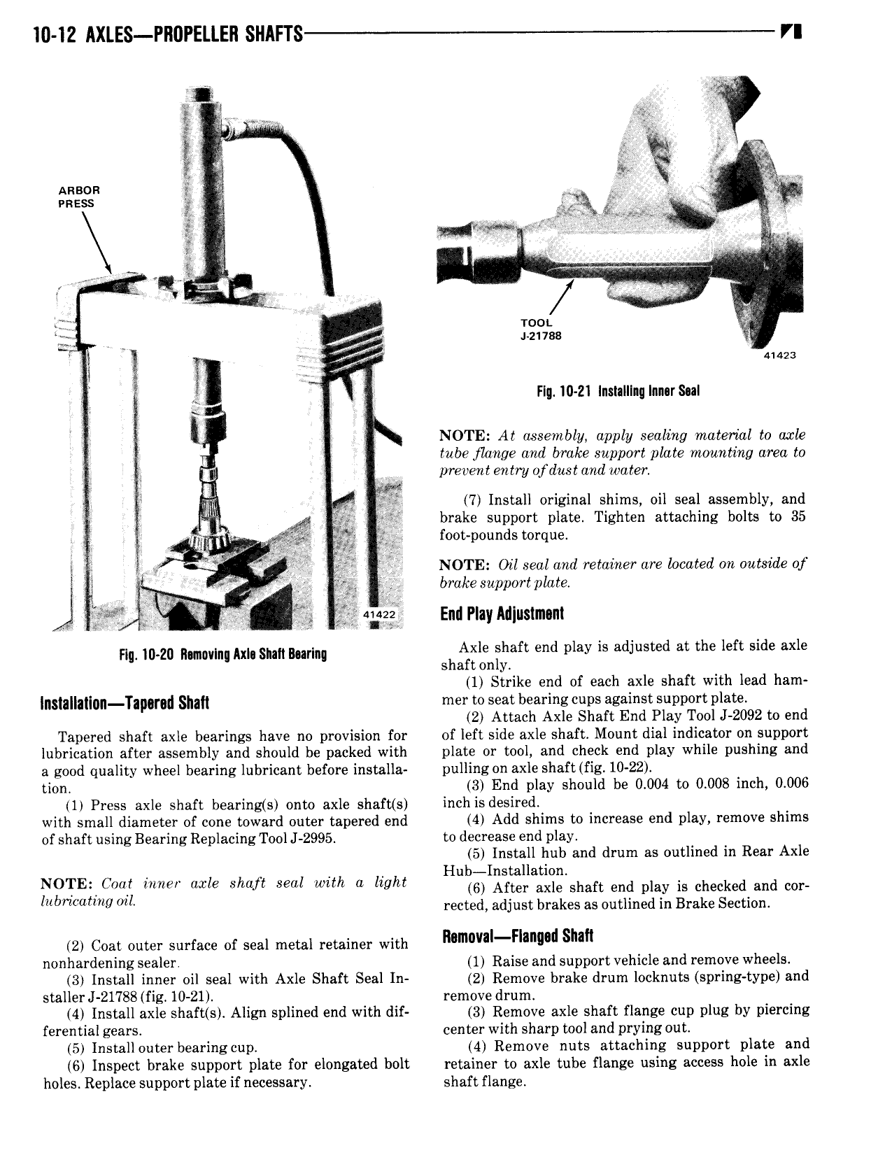
I0 12 AXLES Pll0PElI EIl SHAFI S VI 51 Q t Anson zi T mess A N W I isi I moi W V 4 i zi7ss gy 2 1 me ll I Fig I0 Z1 Instnlllnglnnarsnl NOTE At assembly apply sealing material to axle tube flange and brake support plate mounting area to N prevent entry ofdust and water 4 7 Install original shims oil seal assembly and 4 f brake support plate Tighten attaching bolts to 35 V 4 I foot pounds torque we I gig I V Q E NOTE Ozl seal and retatner are located on outstde of S L age QQ brakesupport plate s xr vis J 2 Q3 vi gg Emi Play Miustmant nw mm nmovlnl Am smh Burl Axle shaft end play is adjusted at the left side axle shaft only 1 Strike end of each axle shaft with lead ham 5 g g m pgrg slim mer to seat bearing cups against support plate 2 Attach Axle Shaft End Play Tool J 2092 to end Tapered shaft axle bearings have no provision for of left side axle shaft Mount dial indicator on support lubrication after assembly and should be packed with plate or tool and check end play while pushing and a good quality wheel bearing lubricant before installa pulling on axle shaft fig 10 22 tion 3 End play should be 0 004 to 0 008 inch 0 006 1 Press axle shaft bearing s onto axle shaft s inch is desired with small diameter of cone toward outer tapered end 4 Add shims to increase end play remove shims of shaft using Bearing Replacing Tool J 2995 to decrease end play 5 Install hub and drum as outlined in Rear Axle Hub Installation lg TF C a f www axle Shaft Seal with a light 6 After axle shaft end play is checked and cor U mlmng ML rected adjust brakes as outlined in Brake Section 2 Coat outer surface of seal metal retainer with R m mn d Sum nonhardening sealer 1 Raise and support vehicle and remove wheels 3 Install inner oil seal with Axle Shaft Seal In 2 Remove brake drum locknuts spring type and staller J 21788 fig 10 21 remove drum 4 Install axle shaft s Align splined end with dif 3 Remove axle shaft flange cup plug by piercing ferential gears center with sharp tool and prying out 5 Installouter bearing cup 4 Remove nuts attaching support plate and 6 Inspect brake support plate for elongated bolt retainer to axle tube flange using access hole in axle holes Replace support plate if necessary shaft flange