Ford Parts Wiki | GM Parts Wiki
Home | Search | Browse | Marketplace | Messages | FAQ | Guest
|
Technical Service Manual January 1975 |
|
Prev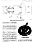
 Next
Next
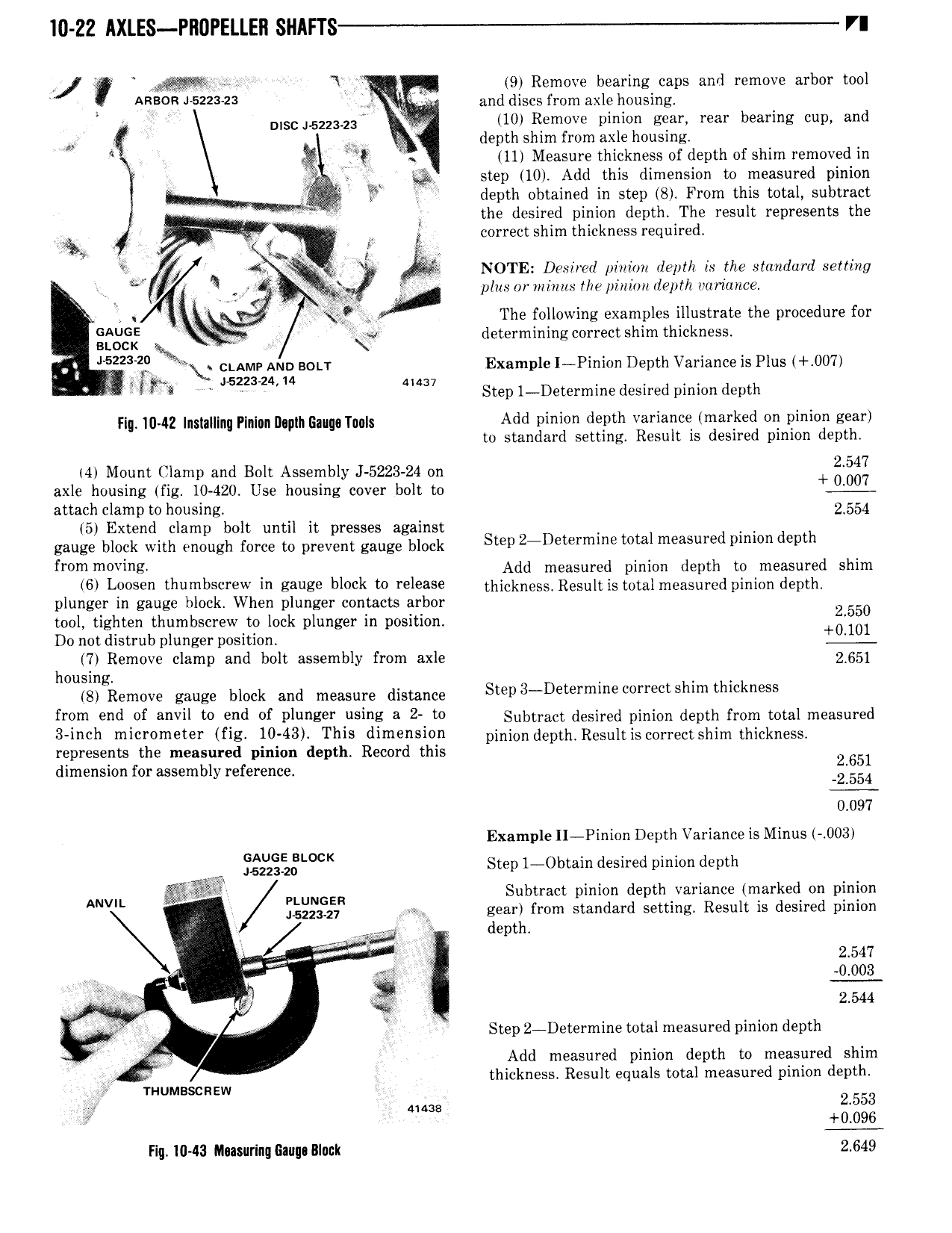
I0 Z2 AXLES PROPELLER Sl IAFl S VI qiI Y V 9 Remove bearing caps and remove arbor tool ARBOR 5223 23 Qi ir and discs from axle housing c D sc 52Z3 z3 10 Remove pinion gear rear bearing cup and M depth shim from axle housing 11 Measure thickness of depth of shim removed in Y Y step 10 Add this dimension to measured pinion i depth obtained in step 8 From this total subtract W rf E the desired pinion depth The result represents the 5 V correct shim thickness required 7 Q Q i NOTE Desire pinion dep 1 is the stmulurd setting r A rt plitsmwizimtsthepinitmdeplh vtmavtce l i l b fd The following examples illustrate the procedure for gcggs L determining correct shim thickness 5zz3 29 cLAMr AND 0LT Example I Pinion Depth Variance is Plus 007 T ipa MZZMAV M 41437 Step 1 Determine desired pinion depth Fiq 10v4Z Inslalllnq PIn unI1 plIiEaug T uls Add pinion depth variance marked on pinion gear to standard setting Result is desired pinion depth 4 Mount Clamp and Bolt Assembly 5223 24 on 354 axle housing fig 10 420 Use housing cover bolt to attach clamp to housing 2554 5 Extend clamp bolt until it presses against gauge block with enough force to prevent gauge block Step 2 D i mlh9 ml measured lhhmh depth from m Vl Add measured pinion depth to measured shim 6 l 0059 h mb Y9 in gauge block W release thickness Result is total measured pinion depth plunger in gauge block When plunger contacts arbor 2 550 tool tighten thumbscrew to lock plunger in position 0 lm Do not distrub plunger position 7 Remove clamp and bolt assembly from axle 2 651 housing 8 Remove gauge block and measure distance Si p3 D tdrml cdrrectshlm thickness from end of anvil to ond of vlnnsor nsing n 2 to Subtract desired pihidh depth from tdtsi measured 3 n h micrometer fu 10 43 This dimension pihichdcpth Rcstiitisccttcctshim thickness represents the measured pinion depth Record this 2 651 dimension for assembly reference 2 554 0 097 Example II Pinion Depth Variance is Minus 003 v i 2 gL cK Step 1 Obtain desired pinion depth PLUNGER Subtract pinion depth variance marked on pinion ANVR 452 21 ear from standard setting Result is desired pinion I N cpt T 2 547 Q 2 sr ist 0 003 m V t 2 544 i 4 W h S Step 2 Determine total measured pinion depth ii Add measured pinion depth to measured shim thickness Result equals total measured pinion depth rnumsscnzw 24 tim 2553 0 096 Hg 1043 Musurinq Gaim Black 2 649