Ford Parts Wiki | GM Parts Wiki
Home | Search | Browse | Marketplace | Messages | FAQ | Guest
|
Technical Service Manual January 1975 |
|
Prev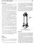
 Next
Next
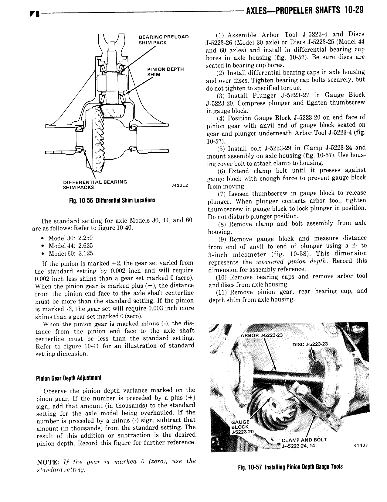
VI AXLES PI10PELLEH SHAFTS I0 29 Banning pizgwau 1 Assemble Arbor Tool J 5223 4 and Discs I SWM PACK J 5223 26 Model 30 axle or Discs J 5223 25 Model 44 and 60 axles and install in differential bearing cup b I Id bores in axle housing fig 10 57 Be sure discs are seated in bearing cup bores J i iii N DEPTH 2 Install differential bearing caps in axle housing and over discs Tighten bearing cap bolts securely but i E do not tighten to specified torque 3 Install Plunger J 5223 27 in Gauge Block Q J 5223 20 Compress plunger and tighten thumbscrew in gauge block 4 4 Position Gauge Block J 5223 20 on end face of 3 3 pinion gear with anvil end of gauge block seated on gear and plunger underneath Arbor Tool J 5223 4 fig 10 57 F E 1 5 Install bolt J 5223 29 in Clamp J 5223 24 and 4 mount assembly on axle housing fig 10 57 Use hous h ing cover bolt to attach clamp to housing 6 Extend clamp bolt until it presses against DIFFERENTIAL BEARING gauge block with enough force to prevent gauge block s nM eAc s JAMIE from moving 7 L tn b bl k t le Fw W 56 r S i pluriger ii n pi Iii ni ci u im i0 i Szniii thumbscrew in gauge block to lock plunger in position The standard setting for axle Models 30 44 and 60 D0 mt disturb plunger p sm n f 1 areasmlows Referm Ggm 10 40 h E Remove clamp and bolt assembly rom axe Mme 30 2250 0u 0l lgRemove gauge block and measure distance M d l44i 2 625 from end of anvil to end of plunger using a 2 to M del60 3125 3 inch micometer fig 10 58 This dimension lf the pinion is marked 2 the gear set varied from represents the measured pimkm depth Record this the standard setting by 0 002 inch and will require dimension for assembly reference 0 002 inch less shims than a gear set marked 0 zero 10 Remove bearing caps and remove arbor tool When the pinion gear is marked plus the distance and discs from axle housing from the pinion end face to the axle shaft centerline 11 Remove pinion gear rear bearing cup and must be more than the standard setting If the pinion depth shim from axle housing is marked 3 the gear set will require 0 003 inch more shims than a gear set marked 0 zero When the pinion gear is marked minus the dis W N tance from the pinion end face to the axle shaft V L centerline must be less than the standard setting 5 9 i 522 2 Refer to figure 10 41 for an illustration of standard s gy msc 5223 2 setting dimension J K V t Pinlnn Gm Depth Adiustmni r Observe the pinion depth variance marked on the V pinon gear If the number is preceded by a plus wg g f if sign add than amount in thousands to the standard I or I l setting for the axle model being overhauled If the I I number is preceded by a minus sign subtract that QAUGE in W amount in thousands from the standard setting The stock result of this addition or subtraction is the desired J62z 2 R pinion depth Record this figure for further reference M r 1 2l xQ 0 T MAN NOTE lf the gem is marked 0 zero use the shnrdurd sernnp Flu I0 51 Inslalllng Pininn I1 nih Ganga Tuul