Ford Parts Wiki | GM Parts Wiki
Home | Search | Browse | Marketplace | Messages | FAQ | Guest
|
Technical Service Manual January 1975 |
|
Prev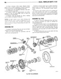
 Next
Next
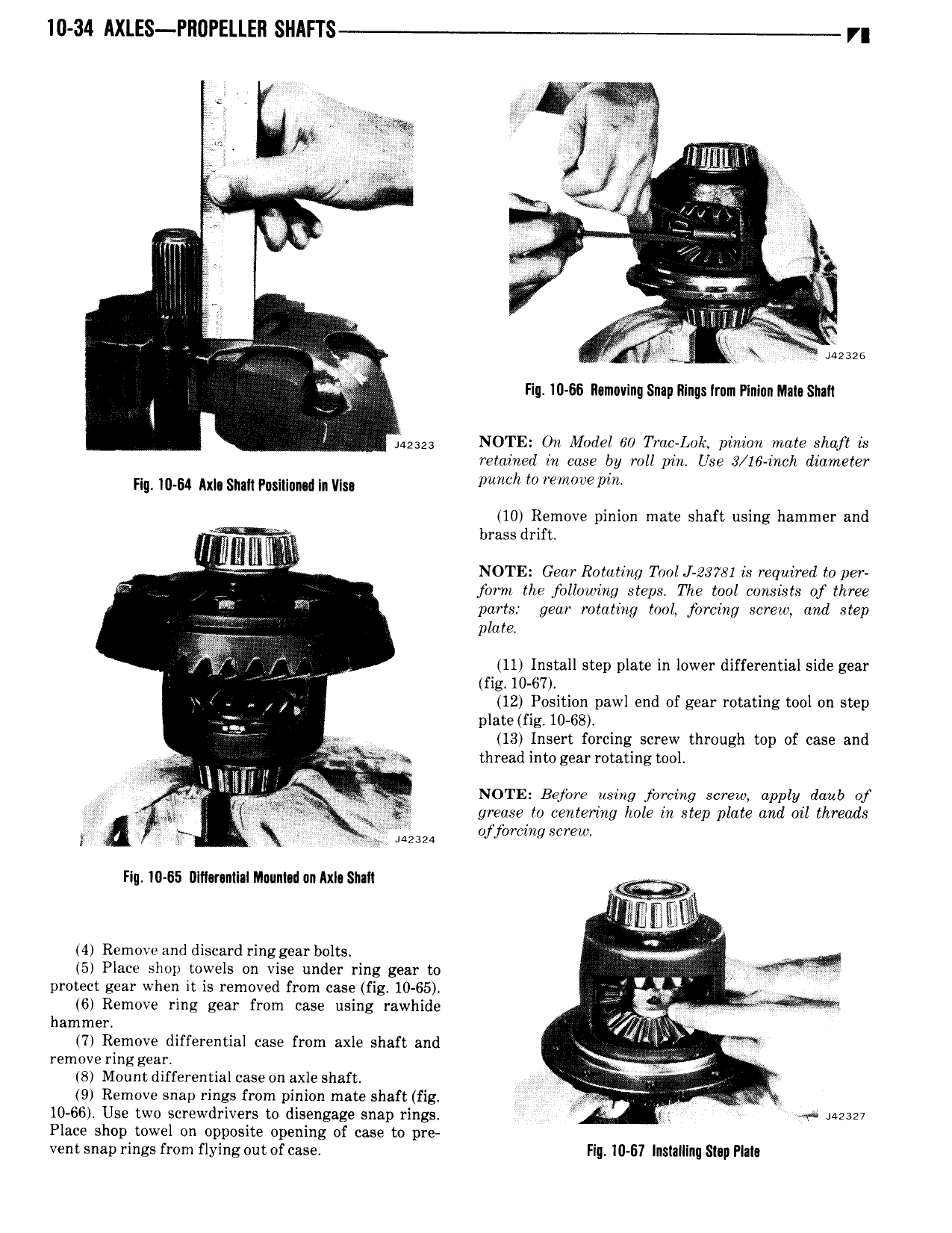
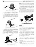
10 34 AXLES Pl10PELLE 1 SHAFf r i W i i lll i lll V F e i r rr if A J gi 17 rr 2 li A 1 i P lll l lll s X gi V l 2s26 l Hu 10 66 11 maving Snap Rings Iram Plninn Mll0S1llli J l MM2 NOTE On Model 60 Truc Lok pinion mate shaft is retained in cose by roll pin Use 3 16 inch diameter Hg 10 64 Axle Shah Pnsitiumd In VIs h LO pm 10 Remove pinion mate shaft using hammer and H A brass drift l A V NOTE Gear Rotating Tool J 23781 is required to per jbrm the following steps The tool consists of three parts gear rotating tool forcing screw and step r 2 plate 11 Install step plate in lower differential side gear i fig 10 67 W b 12 Position paw end of gear rotating tool on step plate fig 10 68 et 13 Insert forcing screw through top of case and M thread intogear rotating tool j1 l l s lll 4 NOTE Before may forcing mea apply daub of g 1 J if 5 grease to centering hole in step plate and oil threads Iii V ojyorcing screw FIq 10 65 DI11mnt1alM unt 1unAxIaSh 1I l s 1 l 4 Remove and discard ringgear bolts i Q 5 Place shop towels on vise under ring gear to protect gear when it is removed from case fig 10 65 ri gy 6 Remove ring gear from case using rawhide jg iv hammer of 71 Remove differential case from axle shaft and Y remove ringgear 8 Mountdifferentialcaseon axle shaft lf 9 Remove snap rings from pinion mate shaft fig Q V 4 H 10 66 Use two screwdrivers to disengage snap rings A i iazsm Place shop towel on opposite opening of case to pre vent snap rings from flying out of case Fig 10 67 Inslllllng Slap Plalo