Ford Parts Wiki | GM Parts Wiki
Home | Search | Browse | Marketplace | Messages | FAQ | Guest
|
Technical Service Manual January 1975 |
|
Prev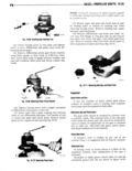
 Next
Next
442316
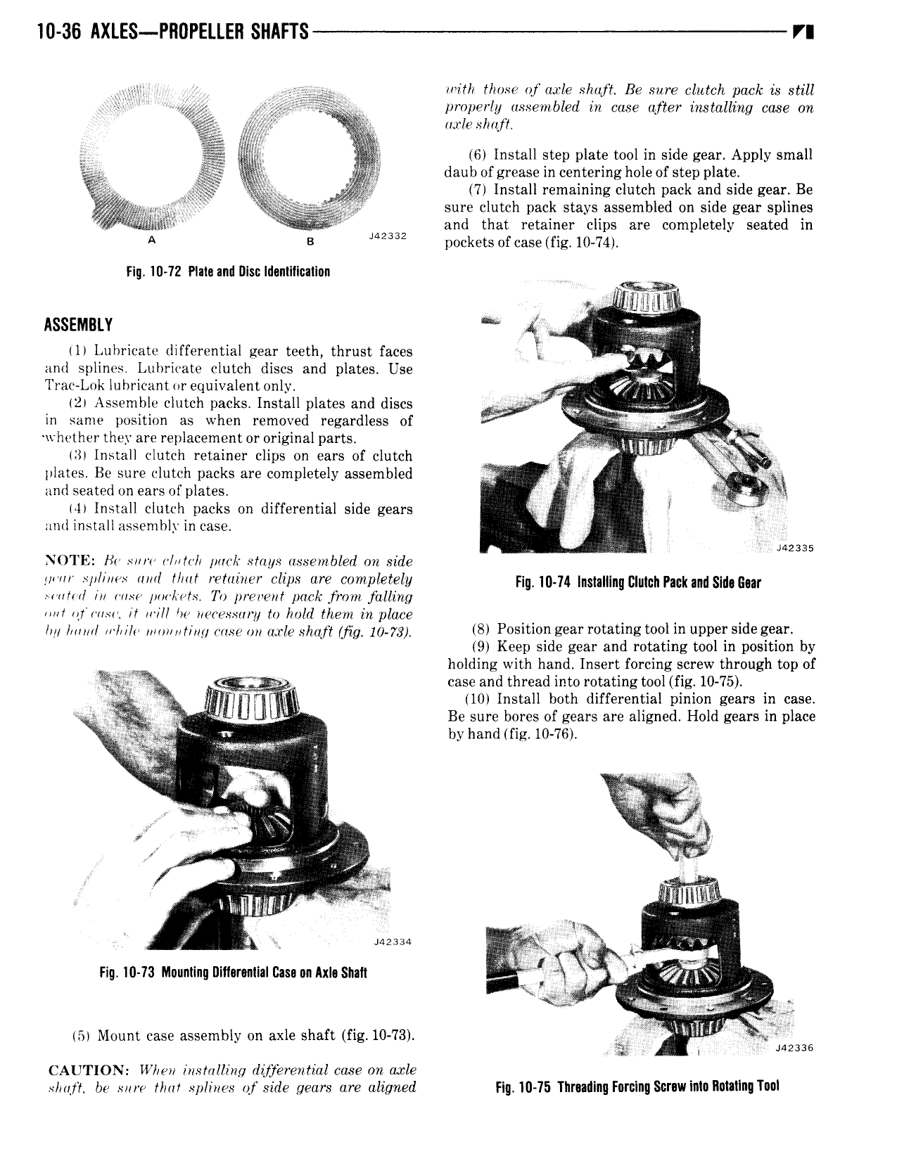
T0 36 IlXLES PRDPElLEIl Sl AFTS VI e j V with l mss of asrle shttfl Be sure clutch puck is still gi V properly assembled in case after installiirzg case on i it umle shalt M or j 6 Install step plate tool in side gear Apply small g Q tail daub of grease in centering hole of step plate k 7 Install remaining clutch pack and side gear Be sure clutch pack stays assembled on side gear splines i and that retainer clips are completely seated in A B M2332 pockets of case fig 10 74 Fig ID 72 Plain and Dlsu lnlanllllcaliun I w llloii Asszmutv 1 Lubricate differential gear teeth thrust faces Q and splines Luhricate clutch discs and plates Use 4 Trac Lok lubricant or equivalent only N 2 Assemble clutch packs Install plates and discs r Vo f 2 in same position as when removed regardless of wht ther they are replacement or original parts 3 Hitwr 3 Install clutch retainer clips on ears of clutch i 4 me plates Bc sure clutch packs are completely assembled I i x Q 9 and seated on ears of plates V M5 4 Install clutch packs on differential side gears nntl install assembly in case J NOTE Ho sow alot park stays assembled on 1212 J 5 y spl r s uml t mt retainer clips ure completely fiu 1 nm u pm and gmgw slum msn porlirafs Tu prevent pack from fullzng ant lgrlwisl t 4 ll be ct ssu y to hold them in place l nm V awa on my that mg 10 73 8 Position eeor rotating tool in upper Side sm 9 Keep side gear and rotating tool in position by holding with hand Insert forcing screw through top of i i 3 V r case and thread into rotating tool fig 10 75 w y 10 Install both differential pinion gears in case W J Be sure bores of gears are aligned Hold gears in place g B j Y by hand fig 10 76 4 n e o s W M 2 in it 1 tix J 9 V VY ol A itil mt it V r msu 5 o L L li Vs Fig I0 73 Muunling I1ill rauliaI 2asu0nAxl SnaI1 l W i 4 ia l Y 5 In my V QQ 5 Mount case assembly on axle shaft f1g 10 73 Y V gy I s 442316 CAUTION V V eu lnstnlling llyjerential case on axle ploy be sure that splines of side gears are aligned Fig 10 75 TlirudinuFurulnqS1 ruwinIuRuutIngTunl