Ford Parts Wiki | GM Parts Wiki
Home | Search | Browse
|
Technical Service Manual January 1975 |
|
Prev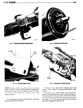
 Next
Next
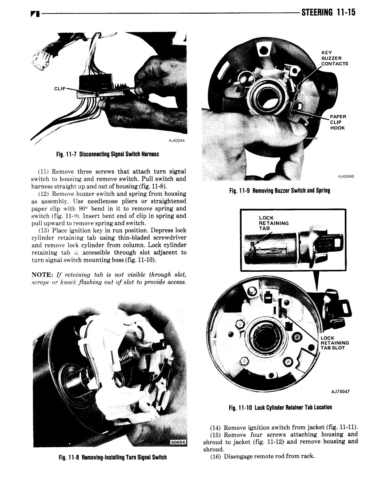
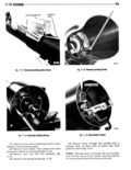
r STEERING 11 15 J J Kev ff J I 1 k suzzsn V QR n I 4 4 w cunmcrs l jdt V l cue B I a V 7 Imran M t 5 cue noun FI 11 1 Diswnnwilng Slunalswllch Ihrnm 111 Remove three screws that attach turn signal switch to housing and remove switch Pull switch and i Aww harness straight up and out of housing fig 11 8 12 Remove buzzer switch and spring from housing HE H g Mmm Bumr SWIM ml sm as assembly Use needlenose pliers or straightened paper clip with 90 bend in it to remove spring and switch fig 11 t Insert bent end of clip in spring and LOCK pull upward to remove spring and switch RETAINING 413 Place ignition key in run position Depress lock TAB cylinder retaining tab using thin bladed screwdriver 7 and remove lork cylinder from column Lock cylinder 1 A retaining Lab is accessible through slot adjacent to I EZf tQ Z turn signal switch mounting boss fig 11 10 NOTE lf retaining tab is not visible through slot scrape or knock flashing out of slot to provide access ri Q i J 0 ii x 4 a E O V 1 qi i 0 Vr LOCK 1 2 w J nzrammc X V Q 9 Q msscor i si E W A J i E r A No 1 V r Annan Flu 11 10 Lock Cyllndur I1 taIn Tab Lmllan e ici 14 Remove ignition switch from jacket Eg 11 11 fi i 15 Remove four screws attaching housing and sosca shroud to jacket fig 11 12 and remove housing and shroud Flu 11 8 11 m vInu ln 1aIlIngT m Signal Swlmh 16 Disengaze m md from k