Ford Parts Wiki | GM Parts Wiki
Home | Search | Browse
|
Technical Service Manual January 1975 |
|
Prev

 Next
Next
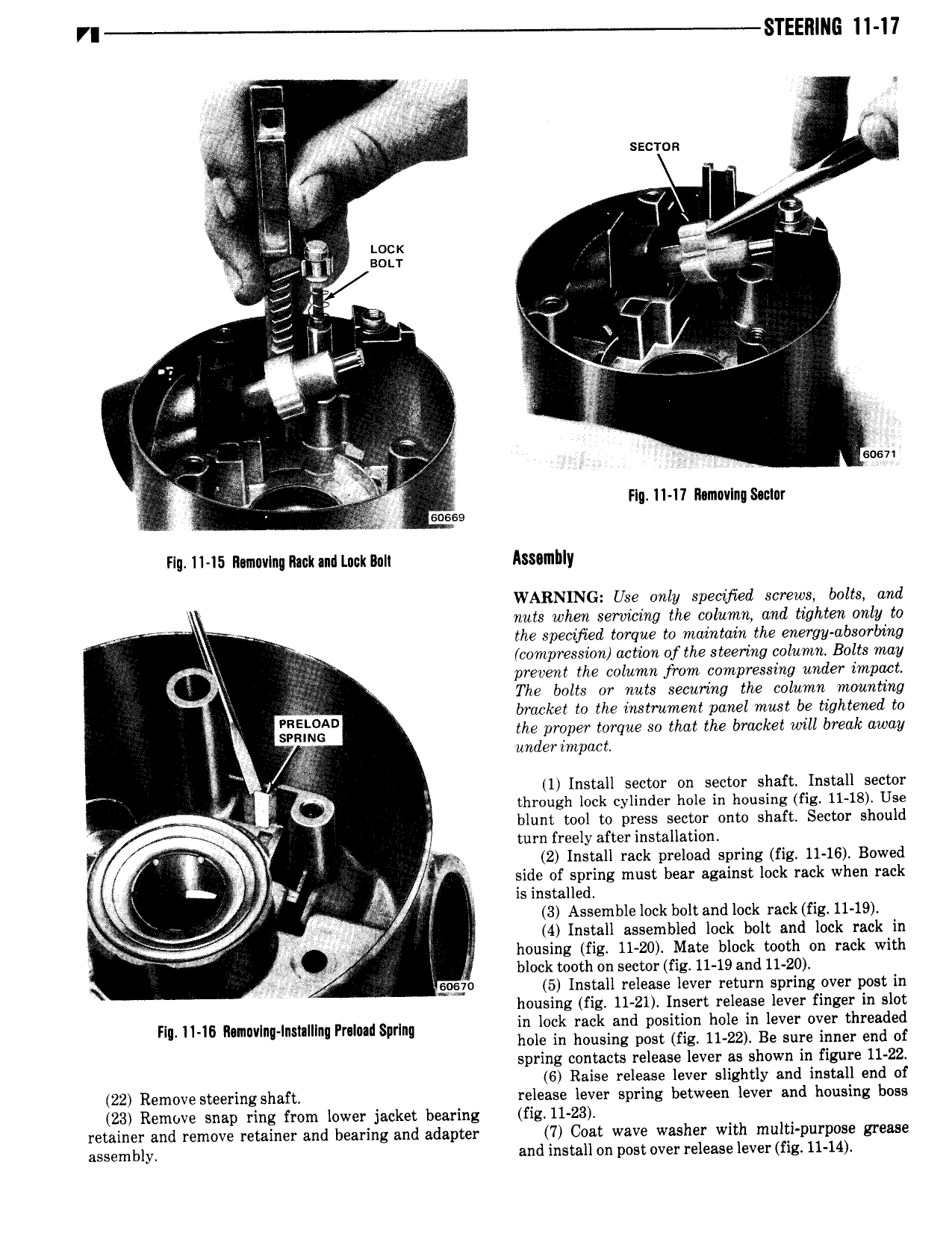
VI STEEl1 l G 11 17 F I ei so 1 Sr V Q V i2 M2 sacmn I It 4 I V I I I 1 1 x g Locx i I if i I I I BOLT 1 V nj T I 7 5 l wl i I i Qt I W i I V i Q 22 4 eo I Q X T M x g V wm f FIq 11 11 Mmcvlnqswinr z com Fig 11 15 llamnvlnn Rack and Luck Ilull lsstlllbly WARNING Use only specihed screws bolts and I r nuts when servicing the column and tighten only to I the specified torque to maintain the energy absorbing V compression action of the steering column Bolts may Ii I prevent the column from compressing under impact Q The bolts or nuts securing the column mounting y bracket to the instrument panel must be tightened to Q ggsmzw the proper torque so that the bracket will break away it under impact l L l i i 1 Install sector on sector shaft Install sector Ps through lock cylinder hole in housing fig 11 18 Use I blunt tool to press sector onto shaft Sector should A I turn freely after installation V I 5 2 Install rack preload spring fig 11 16 Bowed I K y side of spring must bear against lock rack when rack i I 5 o I is installed FTM J 3 Assemble lock bolt and lock rack fig 11 19 4 Install assembled lock bolt and lock rack in i V M V i I I housing fig 11 20 Mate block tooth on rack with ir block tooth on sector fig 11 19 and 11 20 5 9 gage 5 Install release lever return spring over post in housing fig 11 21 Insert release lever finger in slot FI II I6 H I I I III I I II I ln lock rack and position hole in lever over threaded II mw M nu nl nu Spr M hole in housing post fig 11 22 Be sure inner end of spring contacts release lever as shown in figure 11 22 6 Raise release lever slightly and install end of 22 Remove steering shaft release lever spring between lever and housing boss 23 Remove snap ring from lower jacket bearing fig l1 23 retainer and remove retainer and bearing and adapter 7 Coat wave washer with multi purpose grease assembly and install on post over release lever fig 11 14

 Next
Next