Ford Parts Wiki | GM Parts Wiki
Home | Search | Browse
|
Technical Service Manual January 1975 |
|
Prev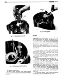
 Next
Next
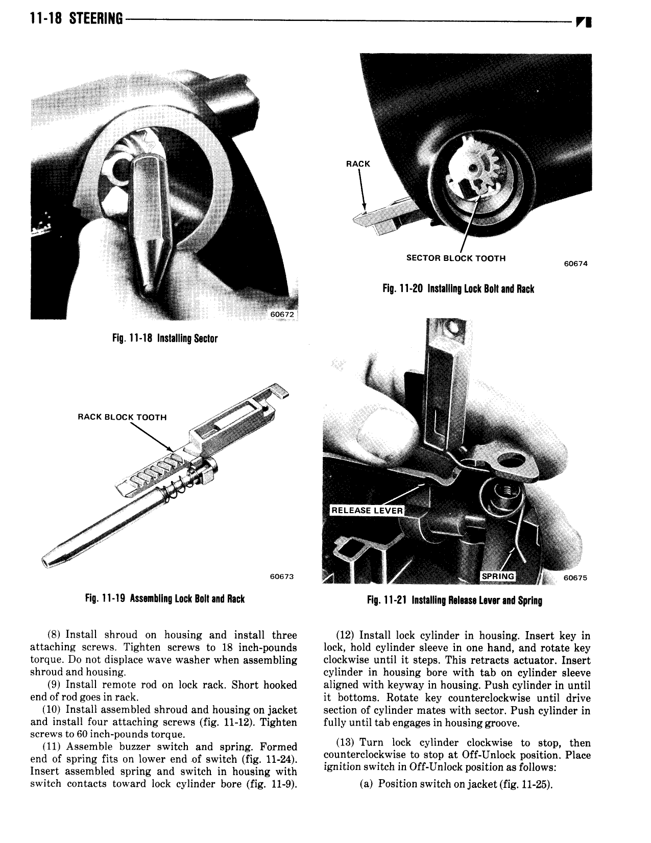
ll 18 STEERING r in ji I e I I s li S mack i in l e le 1 BM ie 4s x g cu 4 Ie gs j 1 I A il SECTOR BLOCK TOOTH 60674 i xii Hg 11 20 lnmlllng Lack Bolt and Rack l 6D 72 t Hg 11 18 Inslalllnqsoclur 1 r 1 eg 1 5 u l 5 W Y Rack stocx Tocm rr l I V i c K I e i 1 E V 4 K e ET A Z ey V t r I T 4 iw Y z ig I eg if 6 7 i y sow Flg 11 19 Issuihllnq Lack Ilnll and Rack Flq 11 21 lnslalllng ll I sa Lmr and Sprlnq 8 Install shroud on housing and install three 12 Install lock cylinder in housing Insert key in attaching screws Tighten screws to 18 inch pounds lock hold cylinder sleeve in one hand and rotate key torque Do not displace wave washer when assembling clockwise until it steps This retracts actuator Insert shroud and housing cylinder in housing bore with tab on cylinder sleeve 9 Install remote rod on lock rack Short hooked aligned with keyway in housing Push cylinder in until end of rod goes in rack it bottoms Rotate key counterclockwise until drive 10 Install assembled shroud and housing on jacket section of cylinder mates with sector Push cylinder in and install four attaching screws fig 11 12 Tighten fully until tab engages in housing groove screws to 60 inch pounds torque 1 d 1 on Assemble buzzer ewaeeh and sprang Formed 13 Tyr Mk wm r k q to then end of spring fits on lower end of switch fig 11 24 Foulggrc Dqtvgqe gfsggplatk FIF k m l l P sw Insert assembled spring and switch in housing with gm mn SW E In n Oc 1 Owl switch contacts toward lock cylinder bore fig 11 9 a Position switch on jacket fig 11 25