Ford Parts Wiki | GM Parts Wiki
Home | Search | Browse
|
Technical Service Manual January 1975 |
|
Prev
 Next
Next
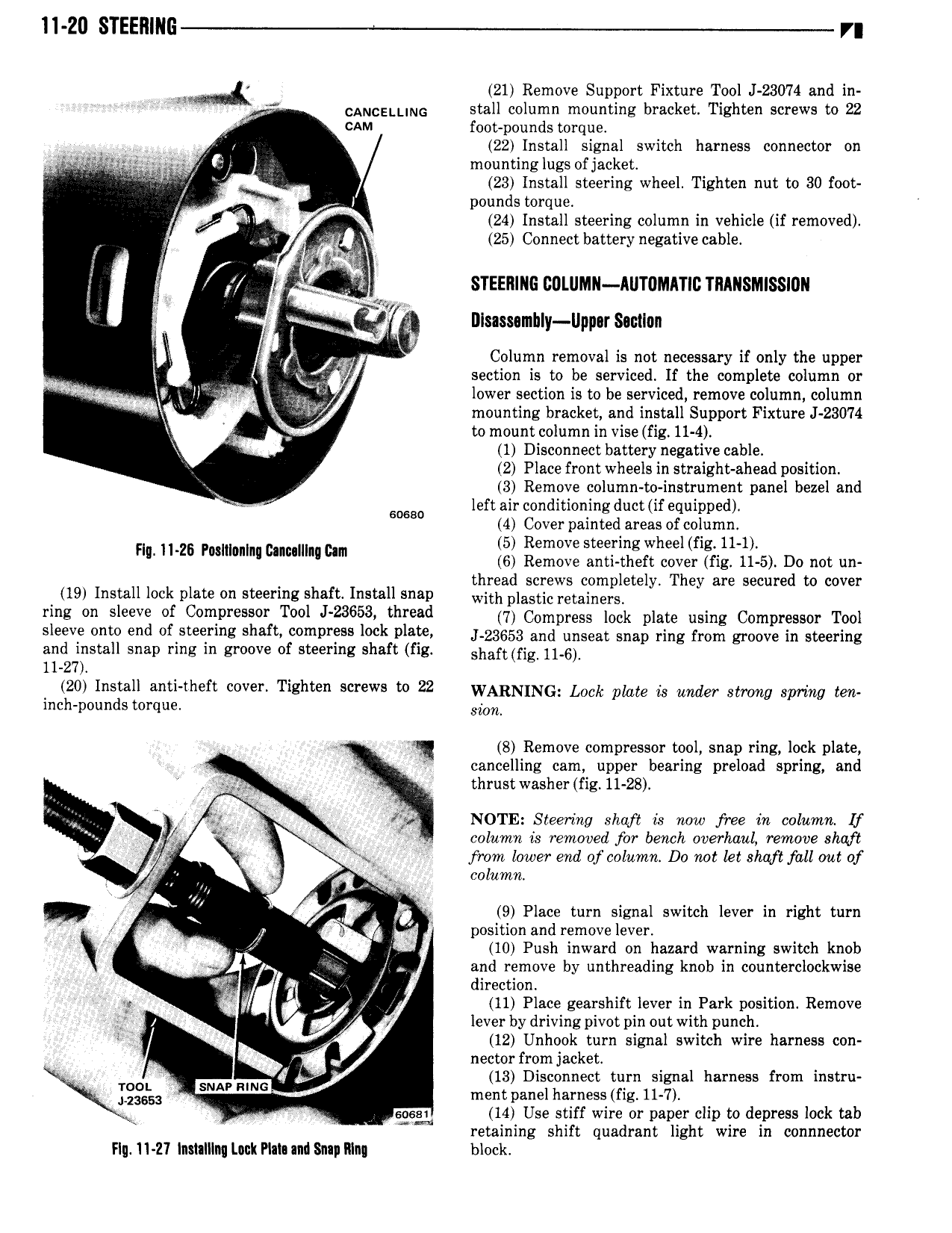
ll 20 STEEIlING r or ni 21 Remove Support Fixture Tool J 23074 and in r CANCELLING stall column mounting bracket Tighten screws to 22 CAM foot pounds torque 22 Install signal switch harness connector on ovens aZ rr n mounting lugs of jacket 23 Install steering wheel Tighten nut to 30 foot I i l pounds torque A I1 M 24 Install steering column in vehicle if removed X 1 t A 25 Connect battery negative cable I C7 MM STEERING DOLlIMN llUTOMATID TRANSMISSION f I V m DIsassamhly Upp rS llon r t 2 i r o pt Column removal is not necessary if only the upper r ir xg section is to be serviced If the complete column or t ai lrqu i ll lower section is to be serviced remove column column lf mounting bracket and install Support Fixture J 23074 to mount column in vise fig 11 4 i 1 Disconnect battery negative cable 2 Place front wheels in straight ahead position 3 Remove column to instrument panel bezel and 50680 left air conditioning duct if equipped 4 Cover painted areas of column 5 Remove steering wheel fig 11 1 F ll ZB Posmonlnl cnmllll cm 6 Remove anti theft cover fig 11 5 Do not un th d l t l Th d t 19 Install lock plate on steering shaft Install snap wi aola i t 1I2 B y ey are secure 0 cover ring on sleeve of Compressor Tool J 23653 thread 7 Compress lock moto using Compressor Tool sleeve onto end of steering shaft compress lock plate z3653 and rmsoor Snap rmg from groove in Steering and install snap ring in groove of steering shaft fig Sh8 fig 11 6 11 27 i 50 lniltail anti theft cover Tighten screws to 22 WARNING Lock plate is under Srmng Spy my gen nc poun s orque o o r lm 8 Remove compressor tool snap ring lock plate cancelling cam upper bearing preload spring and 2 9 V V no thrustwasher fig 11 28 I vi NOTE Steering shqft is now free in column lf 4 W ge column ts removed for bench overlvauL remove shaft gt A go from lower eml of column Do not let shaft fall out of K V Ura l A column Q 9 Place turn signal switch lever in right turn to of mr position and remove lever or n IO Push inward on hazard warning switch knob and remove by unthreading knob in counterclockwise i 4 B 7 direction I A I x 11 Place gearshift lever in Park position Remove i lever by driving pivot pin out with punch i 3 12 Unhook turn signal switch wire harness con nectorfrom jacket TOOL SNAP RING f g 13 Disconnect turn signal harness from instru 23653 ment panel harness fig 11 7 V cool 14 Use stiff wire or paper clip to depress lock tab retaining shift quadrant light wire in ccmmector Fly 11 21 lnslalllnq Lack Plala and Snap lllng block