Ford Parts Wiki | GM Parts Wiki
Home | Search | Browse
|
Technical Service Manual January 1975 |
|
Prev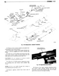
 Next
Next
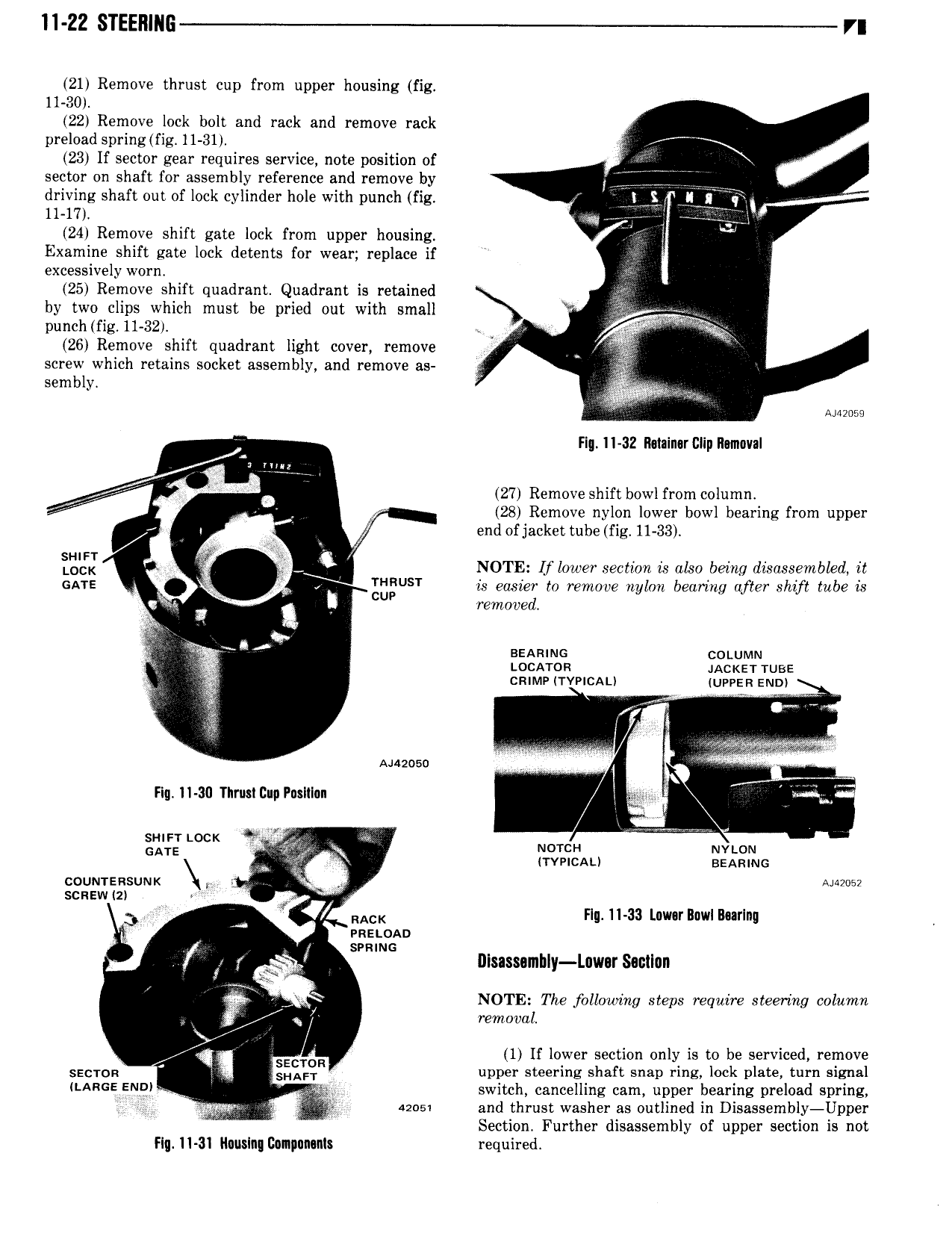
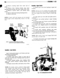
11 ZZ STEEI11116 r 21 Remove thrust cup from upper housing fig 11 30 22 Remove lock bolt and rack and remove rack preload spring fig 11 31 23 If sector gear requires service note position of sector on shaft for assembly reference and remove by V V Q 7 V driving shaft out of lock cylinder hole with punch fig V VQ V r 11 17 Q 77 j 24 Remove shift gate lock from upper housing Examine shift gate lock detents for wear replace if excessively worn 25 Remove shift quadrant Quadrant is retained j by two clips which must be pried out with small N 7 27 punch og 11 32 1 26 Remove shift quadrant light cover remove A screw which retains socket assembly and remove as x sembly Y sums Fl 1I 32 R 1ain r Dlip Removal 2 Uwn V 27 Remove shift bowl from column x 28 Remove nylon lower bowl bearing from upper 4 I end ofjacket tube fig 11 33 E I NOTE I f lo wer section is also being disassembled it GATE V T U T is easier to remove nylon bearing after shift tube is obs N CUP removed I lv l n BEAMNG cotuvvm V Locnon 4Ac zr1 use cmmv TYPICAL quppga END rroo if 1 l r V Auzoso l i Fiq 11 30 Thrust Cup Pnslllnn V V VM sr urr Lock r W WWE rrrr GATE ax uovcn Nvtom TYPICAL sEAmuc coumznsuux V Angus scnsw 21 VV 3 RACK Flu 11 33 Lavnrlcwl Imrlnq V V nzn 0A x svnmc V V y 3 I1Isassnmbly Luwar Sacllun J NOTE The following steps require steering column V 7 removal J V l SECTOR 1 If lower section only is to be serviced remove sacron SHAFT upper steering shaft snap ring lock plate turn signal LARGE Eno V switch cancelling cam upper bearing preload spring V nos and thrust washer as outlined in Disassembly Upper i AA Section Further disassembly of upper section is not Flg 11 31 Iluuslng llonpununls required