Ford Parts Wiki | GM Parts Wiki
Home | Search | Browse
|
Technical Service Manual January 1975 |
|
Prev
 Next
Next
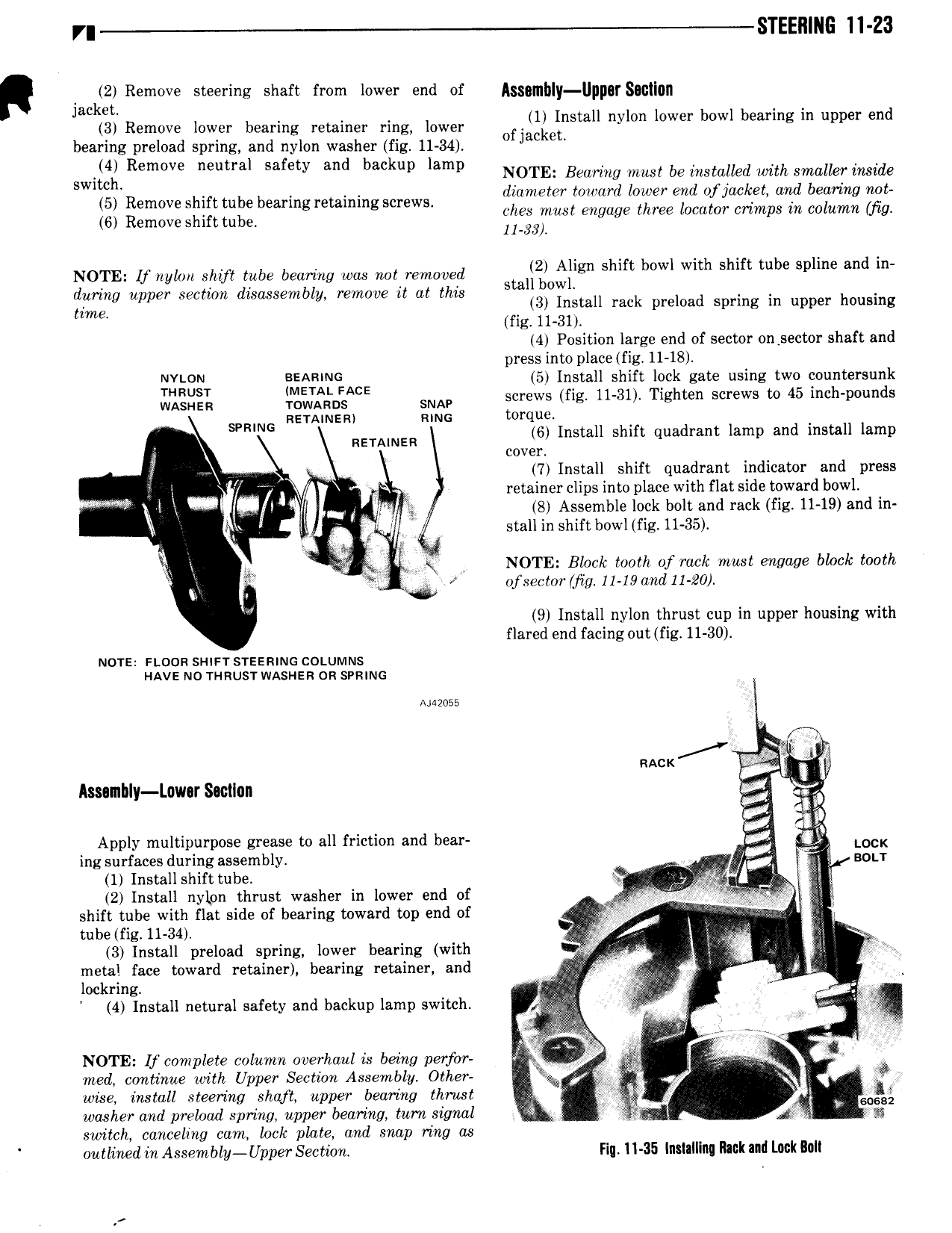
r STEE11lN 11 23 R Q2 Remove steering shaft from lower end of A g y g Smllqn Jac et 3 Remove lower bearing retainer ring lower 1 Install nylon lower bowl bearing in upper end bearing preload spring and nylon washer fig 11 34 0 Jac B Swim Remove neutral safety and backup lamp NOTE Bearing must be installed with smaller inside 5 Remove shift tube bearing retaining screws flilmlmm ggagd Lizlir e L f M7 et my begmng gb 6 Removeshmtube gleggpius g ge ee o orc mps nco umn g NOTE Um lm Shw tube bearing was not mmlwed lg Align shift bowl with shift tube spline and in during upper section disassembly remove it at this Sm w mlm fig Igstall rack preload spring in upper housing 4 Position large end of sector on sector shaft and press into place fig 11 18 NYLON BEARING 5 Install shift lock gate using two countersunk ELSE lr J D A E SNAP screws fig 11 31 Tighten screws to 45 inch pounds SPRING RETAINER mm orirlgkil H h f ad I d H I RETAINER nsta s 1 t qu rant amp an insta amp i cover E I 7 Install shift quadrant indicator and press V V retainerclips into place with flat side toward bowl l 1 i 8 Assemble lock bolt and rack fig 11 19 and in i stall in shift b0wl fig 11 35 i Q P i iv qt V gr NOTE Block tooth of rack must engage block tooth ig f ofsectorgfig 11 19and11 20 9 Install nylon thrust cup in upper housing with flared end facing out fig 11 30 Nora noon suwr srszmuo coturvnns 1 Ave No n mus1 wAsr isn on srmmc 7 i RAcK r wfgtf Assembly Lnwarsactlnn vt 1 2 5 l Apply multipurpose grease to all friction and bear f Q LOCK ingsurfsces during assembly I sou 1 Install shift tube l l 2 Install nylon thrust washer in lower end of y i r shift tube with flat side of bearing toward top end of fz V tubelfig 11 34 hc I 3 Install preload spring lower bearing with r metal face toward retainer bearing retainer and j lockring 4 g 4 Install netural safety snd backup lamp switch 2l s 7 j NOTE lf complete column overhaul is being perfor r sg med continue with Upper Section Assembly Other r is wise install steering shaft upper bearing thrust 2 V i washer and preload spring upper bearing turn signal j 31 switch canceling cam lock plate and snap ring as outlined in Assembly Upper Section Fin ll 35 Iniialllnq Rick and Lock lull