Ford Parts Wiki | GM Parts Wiki
Home | Search | Browse
|
Technical Service Manual January 1975 |
|
Prev
 Next
Next
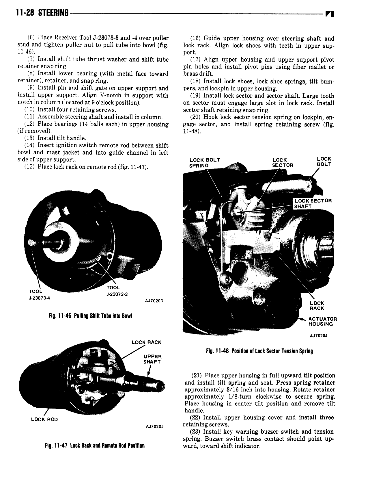
ll 28 STEER N6 VI 6 Place Receiver Tool J 23073 3 and 4 over puller 16 Guide upper housing over steering shaft and stud and tighten puller nut to pull tube into bowl fig lock rack Align lock shoes with teeth in upper sup 11 46 port 7 Install shift tube thrust washer and shift tube 17 Align upper housing and upper support pivot retainer snap ring pin holes and install pivot pins using fiber mallet or 8 Install lower bearing with metal face toward brass drift retainer retainer and snap ring 18 Install lock shoes lock shoe springs tilt bum 9 Install pin and shift gate on upper support and pers and lockpin in upper housing install upper support Align V nctch in support with 19 Install lock sector and sector shaft Large tooth notch in column looated at9o cIock position on sector must engage large slot in lock rack Install 10 Install four retaining screws sector shaft retaining snap ring 11 Assemble steering shaft and install in column 20 Hook lock sector tension spring on lockpin en 12 Place bearings 14 balls each in upper housing gage sector and install spring retaining screw fig if removed 11 48 13 Install tilt handle 14 Insert ignition switch remote rod between shift bowl and mast jacket and into guide channel in left side of upper support LOCK BOLT LOCK LOCK 15 Place lock rack on remote rod fig 11 47 SPRING SE T R BOLT im xx 1 V z 0 SECTOR 4 V j sui l T a X il Or V I c V ir J s I r ferr me agp I r I l 7 U roo Iggjlw zso7 V i umu LOCK Y nacx Flq 1146 I uI n Sl1 l1 uI Im Bowl ACTUATOR r Housmc umm Lock ncx Flu 11 48 Poslllon M Luck S c1nrT nsIon SprIn urns nj I 21 Place upper housing in full upward tilt position 2 A and install tilt spring and seat Press spring retainer F approximately 3 16 inch into housing Rotate retainer approximately 1 8 turn clockwise to secure spring V Place housing in center tilt position and remove tilt handle LUCK ROD V 22 Install upper housing cover and install three Mums retaining screws 23 Install key warning buzzer switch and tension spring Buzzer switch brass contact should point up Fi I1 4 I lntk Rink Illl Illlll IM Putlilnn ward toward shift indicator