Ford Parts Wiki | GM Parts Wiki
Home | Search | Browse
|
Technical Service Manual January 1975 |
|
Prev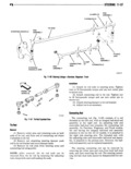
 Next
Next
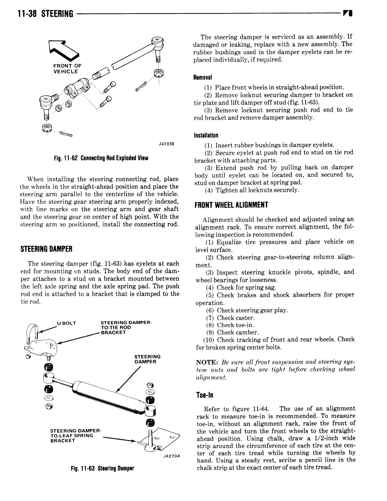
11 38 STEERING VI 3 The steering damper is serviced as an assembly If Q damaged or leaking replace with a new assembly The rubber bushings used in the damper eyelets can be re placed individually if required FRONT OF vziuctz Q 3 I muvaI 3 4 Rf 4 1 Place front wheels in straight ahead position 4 2 Remove locknut securing damper to bracket on g mj tie plate and lift damper off stud fig 11 63 I I 3 Remove locknut securing push rod end to tie i rod bracket and remove damper assembly Inslallatlun 1 Insert rubber bushings in damper eyelets 2 Secure eyelet at push rod end to stud on tie rod Fig I1 62 GonnacIm I1adB pI d dVlnw bracket with attaching pattst 3 Extend push rod by pulling back on damper When installing the steering connecting rod place 3g0 I 21n lLi a T 2t i Jgigfgisg and Secured m the wheels in the straight ahead position and place the 4 Ti htm an locknuts Securely steering arm parallel to the centerline of the vehicle g Have the steering gear steering arm properly indexed with line marks on the steering arm and gear shaft mom WHEELALIGNMENT and the Steering geirpn cenier of high polm with the Alignment should be checked and adjusted using an steering arm so positioned install the connecting rod alignment rackt T0 ensure correct alignment the fop lowing inspection is recommended 1 Equalize tire pressures and place vehicle on STEERING DAMPEH level surface 2 Check steering gear to steering column align The steering damper fig 11 63 has eyelets at each mens end for mounting on studs The body end ofthe dam 3 nspsc gtegring knuckle pivots spindle and per attaches to a stud on a bracket mounted between wheel bearings forlosssnsss the left axle spring and the axle spring pad The push 4 Check Or spying sag rod end is attached to a bracket that is clamped to the 5 Check brakes and shock absorbers for proper U6 0d operation 6 Check steering gear play jg ggggggggijy 3 glI l D 9 Check camber 4 10 Check tracking of front and rear wheels Check Q for broken spring center bolts G e srsemuc DAMPER NOTE Be sure all front snspenszon and steermg sys tem nuts and bolts are tight before checking wheel R alignment 0 7 Tnu In E E 7 Refer to figure 11 64 The use of an alignment 0 rack to measure toe in is recommended To measure toe in without an alignment rack raise the front of TEE t mgER the vehicle and turn the front wheels to the straight ggtcgsq ahead position Ltsing chalk draw a 1 2 inch wide sq strip around the circumference of each tire at the cen 2 04 ter of each tire tread while turning the wheels by hand Using a steady rest scribe a pencil line in the Flg 11 63 S1 r n Dlnpur chalk strip at the exact center of each tire tread