Ford Parts Wiki | GM Parts Wiki
Home | Search | Browse
|
Technical Service Manual January 1975 |
|
Prev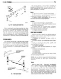
 Next
Next
142706
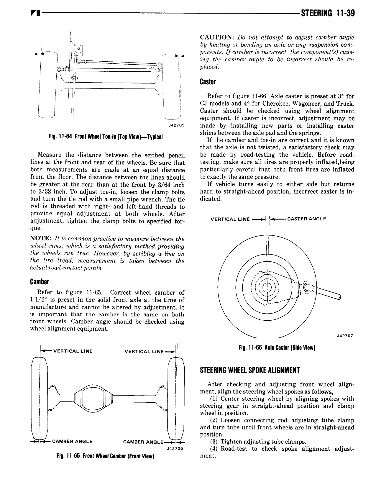
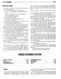
VI STEEll llG ll 39 I CAUTION D0 not attempt to adjust camber angk J so by heating or bending an axle or any suspension com s 3 ponents Ifcamber is incorrect the componentts caus 5 l i ing the cumber angle to be incorrect should be re e e e U l d r l Castor l Refer to figure 11 66 Axle caster is preset at 3 for J ll CJ models and 4 for Cherokee Wagoneer and Truck ll L U Caster should be checked using wheel alignrnent l equipment If caster is incorrect adjustment may be M27 5 made by installing new parts or installing caster shims between the axle pad and the springs F Him Fmmwmll T lT p w l Tw If the camber and toe in are correct and it is known that the axle is not twisted a satisfactory check may Measure the distance between the scribed pencil be made by 3d T l E the V hlcl Before 03d lines at the front and rear ofthe wheels Be sure that testing make sure all tires are properly i fl d b i s both measurements are made at an eqnsl distance particularly careful that both front tires are inflated from the floor The distance between the lines should to X 2 lY the Same P 5 be greater at the rear than at the mnt by 3 64 inch If vehicle turns easily to either side but returns to 3 32 inch To adjust me in loosen the clamp bolts hard to straight ahead position incorrect caster is in and turn the tie rod with a small pipe wrench The tie dicated rod is threaded with right and left hand threads to provide equal adjustment at both wheels After adjustment tighten the clamp bolts to specified tor VERTICAL LINE l tcAs1 ER ANGLE que NOTE It is common practice to measure between the wheel rims which is a satisfactory method proinhiing the wheels mn true However by scribing a line on the tire tread measurement is taken between the actual road contact points N x e j i i Z x x Refer to figure 11 65 Correct wheel camber of i l l f i l r i 1 1 2 is preset in the solid front axle at the time of manufacture and cannot be altered by adjustment It V as important that the camber is the same on beth front wheels Camber angle should be checked using wheel alignment equipment l vsrmcal une velzricm uns nl 11 66 Am nam sm mw i STEERING WHEEL SPUKE ALIGNMEIIT l After checking and adjusting front wheel align ment align the steering wheel spokes as follows l 1 Center steering wheel by aligning spokes with steering gear in straight ahead position and clamp i wheel in position 2 Loosen connecting rod adjusting tube clamp and turn tube until front wheels are in straight ahead l position umass Aust cnmnzn Anon 3 Tighten adjusting tube clamps 142706 4 Road test to check spoke alignment adjust Fl ll 55 From vllnl Camh r Fmnlvl w ment