Ford Parts Wiki | GM Parts Wiki
Home | Search | Browse
|
Technical Service Manual January 1975 |
|
Prev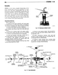
 Next
Next
442146
142145
442141
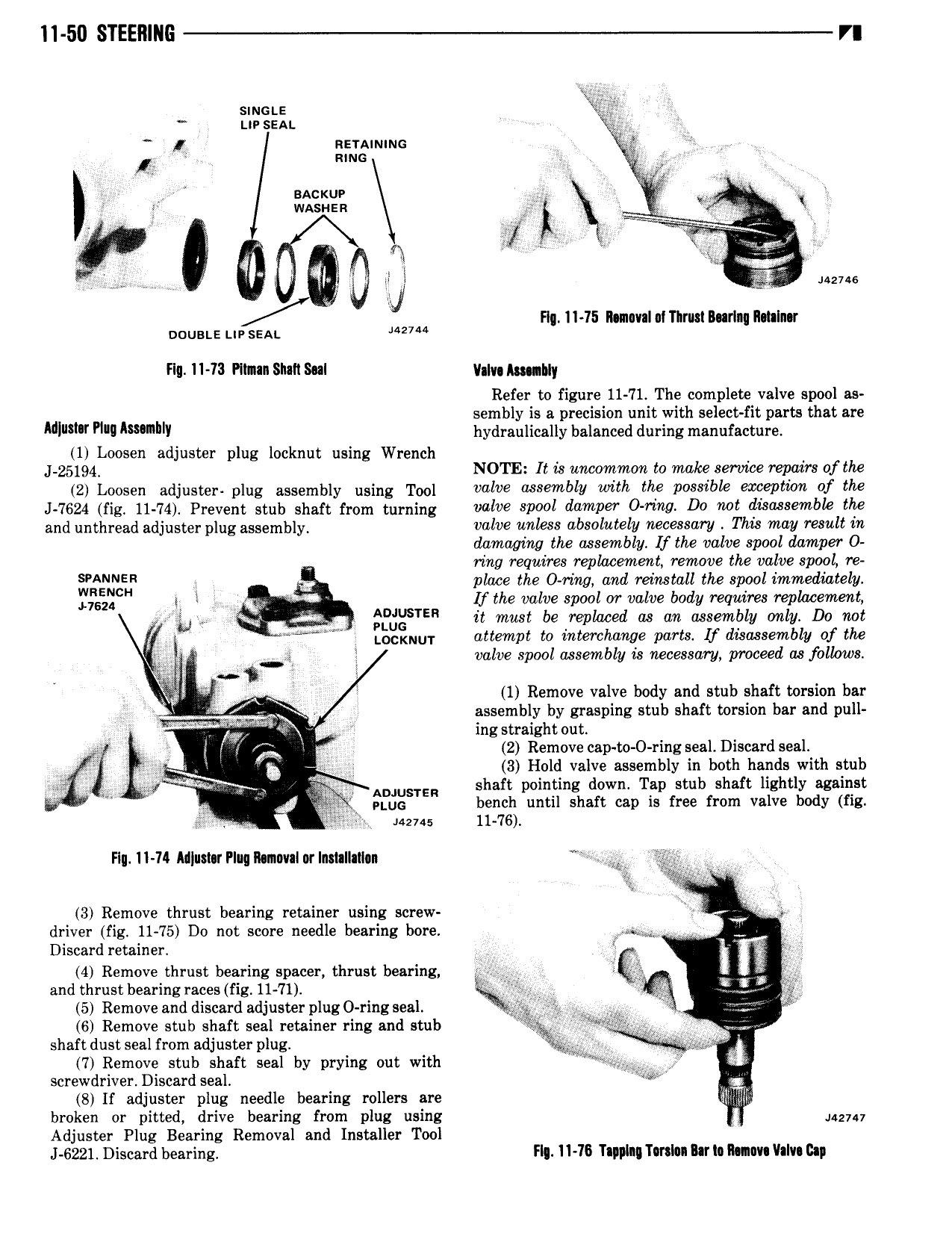
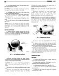
11 50 STEERING V smcae ur sean gg nrranunnc i mum A 2 sAc uv 3 i j washes Yi lr F 1 a igify W 442146 Fl 11 15 11 movala1Tlrus1 Burlnq I1 t I r oousas uv sem 2 Flq 11 13 Pllnan Shall Sal ll lv Amnhly Refer to figure 11 71 The complete valve spool as sembly is a precision unit with select fit parts that are Mum 1 w hydraulically balanced during manufacture 1 Loosen adjuster plug locknut using Wrench J 25194 NOTE It is uncommon to make service repairs ofthe 2 Loosen adjuster plug assembly using Tool valve 7 mbllI with the Possible ewgpllion vf the J 7624 fig 11 74 Prevent stub shaft from turning valve spool damper O ring Do not dikwasemble the and unthread adjuster plug assembly valve unless absolutely necessary This may result in damaging tim assembly lf the valve spool damper 0 ring requires replacement remove the valve spool re NN s y place the 0 ring and reinstall the spool immediately Hsu l l lf the valve spool or valve body requires replacement fd SYE it must be replaced as an assembly only Do not Z LOCKNUT attempt to interchange parts lf disassembly of the g Q s valve spool assembly is necessary proceed aa follows i l 1 Remove valve body and stub shaft torsion bar Q y i r 1 assembly by grasping stub shaft torsion bar and pull ingstraightout W j J 2 Remove cap to 0 ring seal Discard seal gf j 5 Q 3 Hold valve assembly in both hands with stub or I 9 ADJUSTER shaft pointing down Tap stub shaft lightly against A Qi pwq bench until shaft cap is free from valve body fig 2 142145 11 76 Flu 11 71 M us1 rPIuq11 n va1 rIn 1al1a11 n Y g 3 Remove thrust bearing retainer using screw driver fig 11 75 Do not score needle bearing bore iur g T Discard retainer 4 Remove thrust bearing spacer thrust bearing L Zlgs 4 and thrust bearing races fig 11 71 K Ee Q 5 Remove and discard adjuster plug O ring seal 2 r 6 Remove stub shaft seal retainer ring and stub 1 V i U shaft dust seal from adjuster plug Y 7 Remove stub shaft seal by prying out with i i screwdriver Discard seal ll ww W S lf adjuster plug needle bearing rollers are lilhliili broken or pitted drive bearing from plug using 442141 Adjuster Plug Bearing Removal and Installer Tool J 6221 Discard bearing Fl 11 76 Tapping Tmlnn In 1 man 1I Iv Bap