Ford Parts Wiki | GM Parts Wiki
Home | Search | Browse | Marketplace | Messages | FAQ | Guest
|
Technical Service Manual January 1975 |
|
Prev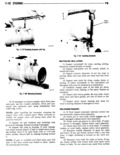
 Next
Next
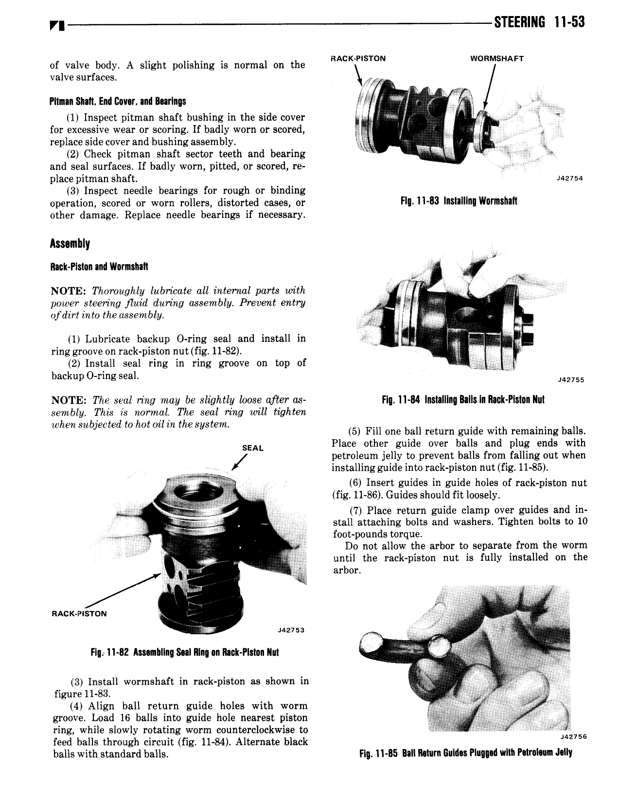
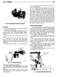
fl STEERING ll 53 of valve body A slight polishing is normal on the RACKIPISWN WORMSHAFT valve surfaces I Ilm nSIa1tEn1ll20v r n1lB rlng 1 Wi 5 W 1 Inspect pitman shaft bushing in the side cover I Y I X for excessive wear or scoring If badly worn or scored 6 l Q replace side cover and bushing assembly lg M I 2 Check pitman shaft sector teeth and bearing W e and seal surfaces If badly worn pitted or scored re place pitm an shaft 4 75 3 Inspect needle bearings for rough or binding operation scored or worn rollers distorted cases or Fl ll B3 l lll II Wvmilllll other damage Replace needle bearings if necessary Aswnlnly Rack Plslan and Vl r1n haIl 5 k i I NOTE Thoroughly lnbiicate all internal parts with I I V M power steering fluid during assembly Prevent entry 5 wl I of dirt into the assembly I 5gi e 3 1 Lubricate backup O ring seal and install in hi 1 ring groove on rack piston nut fig 11 82 Wi 2 Install seal ring in ring groove on top of T rf backup 0 ring seal M2 55 NOTE The seal ring may be slightly loose after as Flg ll 84 lnslalllng Blllsln Il ck Pls n llul sembly This is normal The seal ring will tighten when subjected to hat ml M the System 5 Fill one ball return guide with remaining balls SEAL Place other guide over balls and plug ends with petroleum jelly to prevent balls from falling out when installingguide into rack piston nut fig 11 85 6 Insert guides in guide holes of rack piston nut fig 11 86 Guides should fit loosely V i QTQZM 7 Place return guide clamp over guides and in c stall attaching bolts and washers Tighten bolts to 10 M 5 N 1 foot pounds torque 55 i Do not allow the arbor to separate from the worm I Mg until the rack piston nut is fully installed on the 5 gi r arbor V V M I vast aw i g as HH Musa L c Fly 11 82 Amnhllng Sul Mg n Rack Plmn Ilut was p 3 Install wormshaft in rack piston as shown in V mgm 11 83 3 5 4 Align ball return guide holes with worm 1 j j5 gj f groove Load I6 balls into guide hole nearest piston Y ring while slowly rotating worm counterclockwise to xii 156 feed balls through circuit fig 11 84 Alternate black balls with standard balls Fig ll B5 Ball llvturn Buldn Plugged with P lrnl n Jelly