Ford Parts Wiki | GM Parts Wiki
Home | Search | Browse | Marketplace | Messages | FAQ | Guest
|
Technical Service Manual January 1975 |
|
Prev
 Next
Next
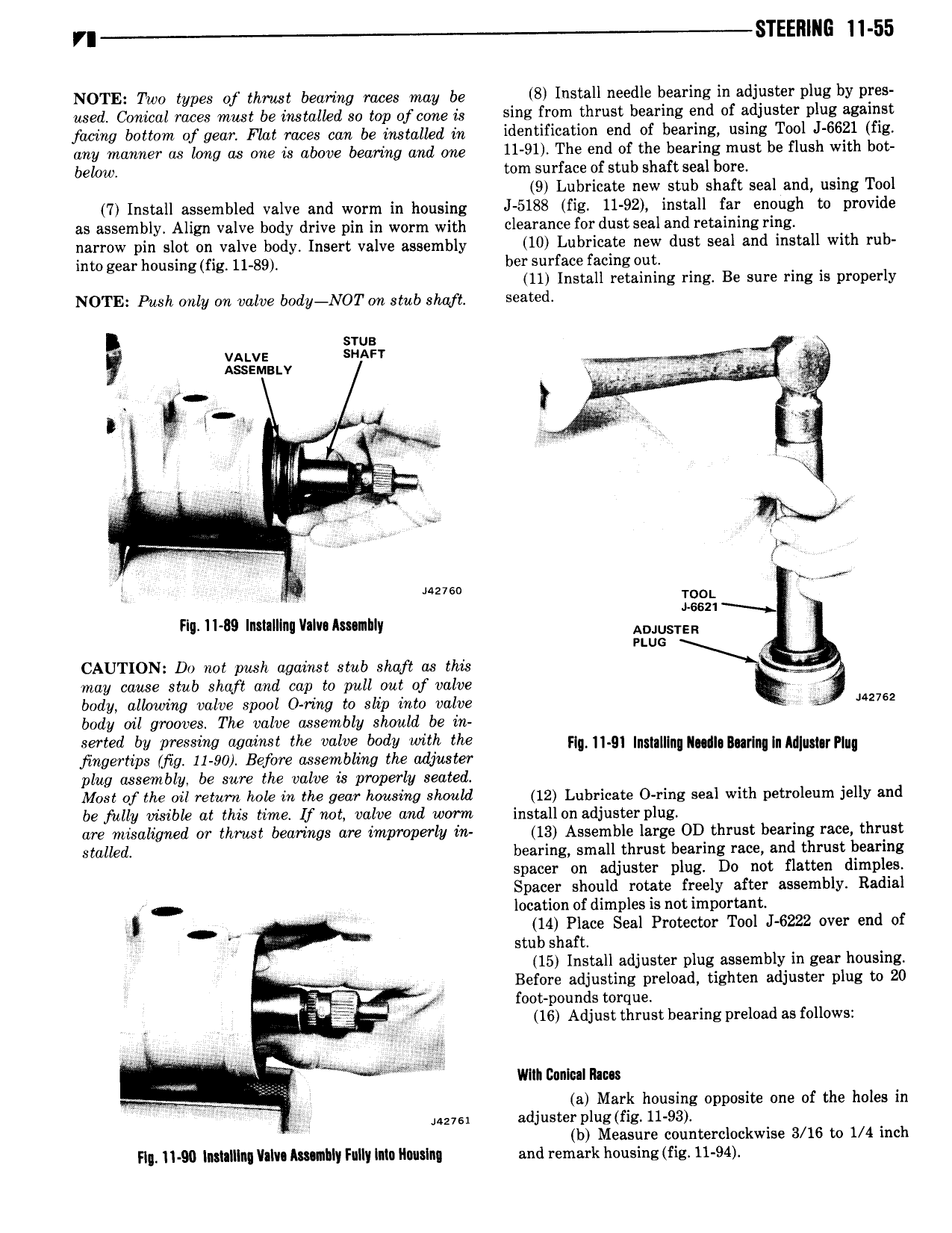
r STEEIllI i 11 55 NOTE Two types of thrust bearing rapes may be 8 Install needle bearing in adjuster plug by pres used Conical raees must be installed so top of cone is sins fl 0m thrust bearing end df adjuster PNZ against facing bottom of gear Flat mpeg can be installed in identification end of bearing using Tool J 6621 fig any manner as long as one is abape bearing and ang 11 91 The end of the bearing must be flush with bot below tom surface of stub shaft seal bore 9 Lubricate new stub shaft seal and using Tool 7 Install assembled valve and worm in housing J 5188 fig 11 92 install far enough to provide as assembly Align valve body drive pin in worm with 0l s OY dust ssal and T t l l B i E narrow pin slot on valve body Insert valve assembly 10 Lubrlcats NW dust seal and install with ub into gear housing fig 11 89 her surface facing out 11 Install retaining ring Be sure ring is properly NOTE Push only on valve body NOT on stub shaft Seated svus V VALVE SHAFY Y 5 As EM v o 3 4 1 sx 2 tif l t al l V or i nemo TOOL tse21 Fm 11 B9 Installlnu llaIv Ammhly ADJUSTER J unc CAUTION Do not pu sh against stub shaft as this may cause stub shaft and cap to pull out of valve body allowing valve spool O ring to slip into valve 2762 body oil grooves The valve assembly should be in serted by pressing against the valve body with the pg g Inmmn mul B rl I M m H fingertips fig 11 90 Before assembling the adjuster U u W n lu r uq plug assembly be sure the valve as properly seated Most of the oil return hole in the gear housing should 12 Lubricate 0 ring seal with petroleum jelly and be fully visible at this time lf not valve and worm install on adjuster plug are misaligned or thrust bearings are improperly in 13 Assemble large OD thrust bearing race thrust stalled bearing small thrust bearing race and thrust bearing spacer on adjuster plug Do not flatten dimples Spacer should rotate freely after assembly Radial V W location of dimples is not important 4 Q 14 Place Seal Protector Tool J 6222 over end of I stub shaft V 15 Install adjuster plug assembly in gear housing Before adjusting preload tighten adjuster plug to 20 jb foot pounds torque E L gr 16 Adjust thrust bearing preload as follows me lllllh Donlullhm vg I a Mark housing opposite one of the holes in Musa adjuster plug fig 11 93 W b Measure counterclockwise 3 16 to 1 4 inch F1 11 90 lmlalllng llalu humbly Fully lata llwslng and remark housing fig 11 94