Ford Parts Wiki | GM Parts Wiki
Home | Search | Browse | Marketplace | Messages | FAQ | Guest
|
Technical Service Manual January 1975 |
|
Prev
 Next
Next
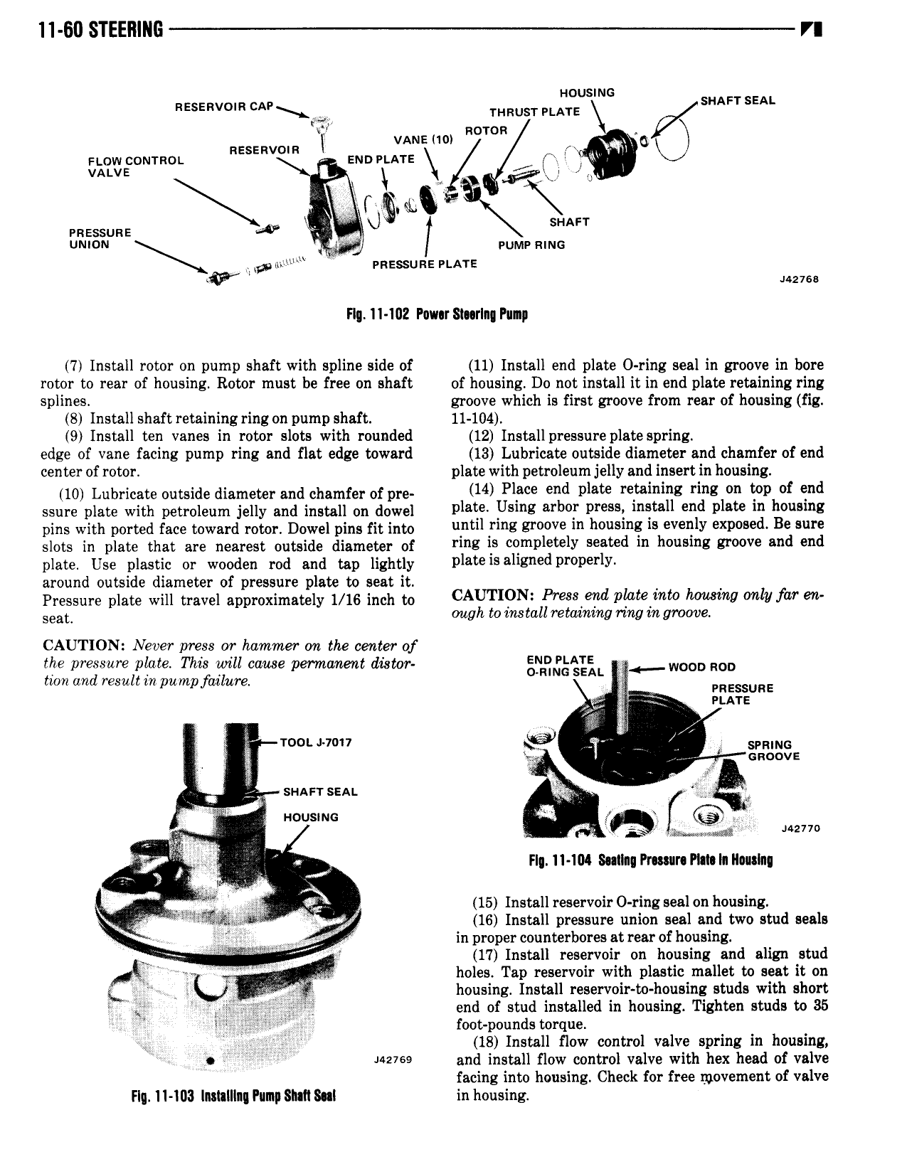
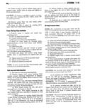
11 60 STEERING VI Housms nssssvom CAP X THRUST PLATE S AFT SEAL K RDTOR N nesznvom i VANEIW rs 6 now common mortar u vaavs L VA gh Q i rnsssuns QV i K f SHAFT UNION V wmv smc A mv in on nessus PLATE uzvss Fly 11 102 Puwur SU rIn Pun 7 Install rotor on pump shaft with spline side of 11 Install end plate 0 ring seal in groove in bore rotor to rear of housing Rotor must be free on shaft of housing Do not install it in end plate retaining ring splines groove which is first groove from rear of housing fig 8 Install shaft retaining ring on pump shaft 11 104 9 Install ten vanes in rotor slots with rounded 12 Install pressure plate spring edge of vane facing pump ring and flat edge toward 13 Lubricate outside diameter and chamfer of end center of rotor plate with petroleum jelly and insert in housing 10 Lubricate outside diameter and chamfer of pre 14 Plnee end Plate neevnnlng ng nn nm f end ssure plate with petroleum jelly and install on dowel n ee Usms anno Press netnn end plete In n n mg pins with ported face toward rotor Dowel pins fit into unm fm groove In housing ls evenly eXPooen Be sure slots in plate that are nearest outside diameter of TIRE S omPlot lY sented In nonomg Kroove ond end plate Use plastic or wooden rod and tap lightly Plate is Shlned P P lY around outside diameter of pressure plate to seat it Pressure plate will travel approximately 1 16 inch to CAUTI9Ni Press 7 te n hommg only fn Z Seat ough to znstall rezaznzng rmg zn groove CAUTION Never press or hammer on the center of the pressure ptate This rvill cause permanent dLstor gnRn h L Sr w D HOD tron and result rn pumpfiulure V rw gsgiiuns J2 2 V E 1 ooL 1V7o11 6 E SPRING 5 il uuocvs i JK V sn msr sein I 1 I aousmc I i r M Mum rs FI Il 104 Sallam Pr mr Hm In Ilaulnq 2 2 S Q V S i v M 15 Install reservoir O ring seal on housing JF 16 Install pressure union seal and two stud seals V V V in proper counterbores at rear of housing 17 Install reservoir on housing and align stud holes Tap reservoir with plastic mullet to seat it on L T g I was housing Install reservoir to housing studs with short P end of stud installed in housing Tighten studs to 35 V s foot pounds torque j g 2 Zf 18 Install flow control valve spring in housing Mem and install flow control valve with hex head of valve facing into housing Check for free movement of valve Flq I1 ID3 Installing Pump SMI Sal in housing