Ford Parts Wiki | GM Parts Wiki
Home | Search | Browse | Marketplace | Messages | FAQ | Guest
|
Technical Service Manual January 1975 |
|
Prev
 Next
Next
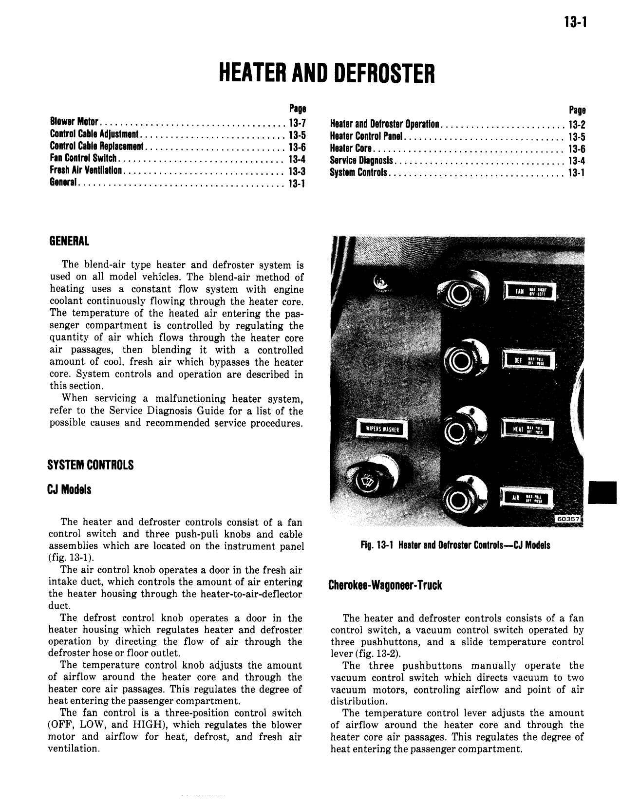
I3 l Pm Pano lllowor Motor 4 4 13 7 Ilomr and I1 1rost r tlparntlon 4 13 2 Control Cable ltl mnn1 4 13 5 ll at r Control Pml 13 5 Control Cahln ll p1 c m n1 13 6 llomr Con 1345 Fan Control Switch 4 4 4 I3 I 8 rv1c Dlaqnnsls 4 13 4 Fmt Alr V tII tIon 4 13 3 Sym Control 13 1 lltlthl 4 13 1 GENERAL g i V V The blend air type heater and defroster system is i fe used on all model vehicles The blend air method of T heating uses a constant flow system with engine coolant continuously flowing through the heater core 4 The temperature of the heated air entering the pas senger compartment is controlled by regulating the Q quantity of air which flows through the heater core it air passages then blending it with a controlled amount of cool fresh air which bypasses the heater m core System controls and operation are described in I this section i When servicing a malfunctioning heater system refer to the Service Diagnosis Guide for a list of the possible causes and recommended service procedures Q Q Pi SYSTEM l20llTll0LS KW cn noun J i The heater and defroster controls consist of a fan control switch and three push pull knobs and cable assemblies which are located on the instrument panel HI l3 l ll l l nl WTWW c l l U M l l fig 13 1 The air control knob operates a door in the fresh air intake duct which controls the amount of air entering gMmk w nm Truuk the heater houstng through the heater to air deflector duct The defrost control knob operates a door in the The heater and defroster controls consists of a fan heater housing which regulates heater and defroster control switch a vacuum control switch operated by operation by directing the flow of air through the three pushbutoons and a slide temperature control defroster hose or floor outlet lever fig 13 2 The temperature control knob adjusts the amount The three pushbuttons manually operate the of airflow around the heater core and through the vacuum control switch which directs vacuum to two heater core air passages This regulates the degree of vacuum motors controling airflow and point of air heat entering the passenger compartment distribution The fan control is a three position control switch The temperature control lever adjusts the amount OFF LOW and HIGH which regulates the blower of airflow around the heater core and through the motor and airflow for heat defrost and fresh air heater core air passages This regulates the degree of ventilation heat entering the passenger compartment