Ford Parts Wiki | GM Parts Wiki
Home | Search | Browse | Marketplace | Messages | FAQ | Guest
|
Technical Service Manual January 1975 |
|
Prev
 Next
Next
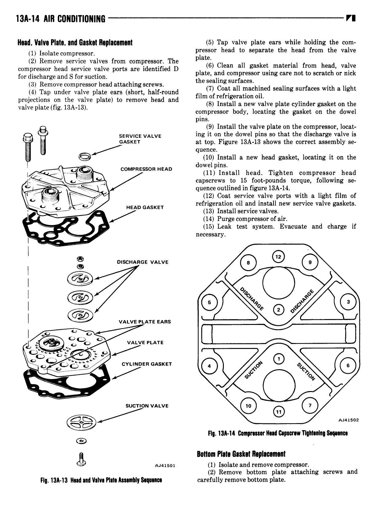
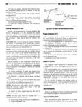
13A 14 AIR GDNDITIGNING VI ll atl V lv Plala and Gask l lhplmmanl 5 Tap valve plate we while holdin the com I Isulawcompresson Ergasor head to separate the head from the valve 2 Remove service valves from compressor The compressor head service valve ports are identified D 1 56 Cyan all gasket material fiom hg Val for discharge and S for suction p a e so compressor using care no o sera or me 3 Remove compressor head attaching screws the zsl ng iuiiacelh d 1 f th 1 ht 4 Tap under valve plate ears short half round 1 8 a Fac like seamg sur aces Wl 3 lg projections on the valve plate to remove head and lm re Hgem mn l Valve plate fig 13A l3 4 8 Install a new valve plate cylinder gasket on the compressor body locating the gasket on the dowel pins 9 Install the valve plate on the compressor locat SERVICE VALVE ing it on the dowel pins so that the discharge valve is A BASKET at top Figure 13A 13 shows the correct assembly se quence 10 Install a new head gasket locating it on the l dowel pins i COMPRESSOR HEAD 11 Install head Tighten compressor head I A f A capscrews to 15 foot pounds torque following se quence outlined in figure 13A 14 Q r i 12 Coat service valve ports with a light film of LU 9 HEAD GASKET rezijgegatiznlloil and initall new service valve gaskets 4 ns a service va ves l rf 14 Purge compressor of air 15 Leak test system Evacuate and charge if me W l l C SS8I y I 3 g Q e as I 4 l in l vows nn sans L gy y OqE O VALVE PLATE O ovtmozn oasxzr 0 ecb L Z ko ici I suenou vstvs Ggh Anim Q Fl 13A 14 canpnmr lla www Tl M nl 8 q m Bottom Plal lla k l ll pl c n t sensor 1 Isolate and remove compressor 2 Remove bottom plate attaching screws and Flq 13A 13 llull nil lhlvt PIII Amnllly Simllu carefully remove bottom plate