Ford Parts Wiki | GM Parts Wiki
Home | Search | Browse | Marketplace | Messages | FAQ | Guest
|
Technical Service Manual January 1975 |
|
Prev
 Next
Next
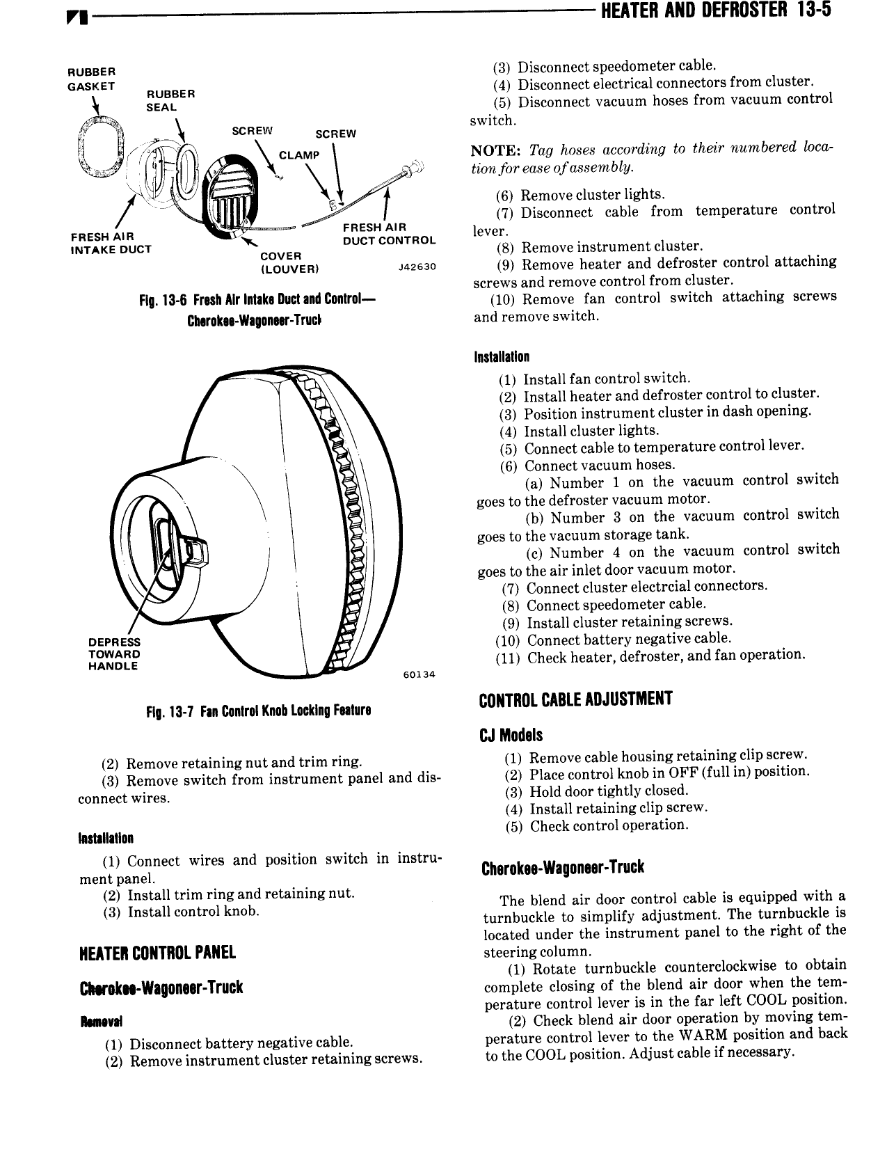
VI HEATER AND DEFNIISTEII I3 5 RUBBER 3 Disconnect speedometer cable GASKET RUBBER 4 Disconnect electrical connectors from cluster E SEAL 5 Disconnect vacuum hoses from vacuum control l SCREW SCREW switch gi ci AMv NOTE Tag hoses uccording to their numbered loco isasl F l j twnfoireaseofossembly x w rv W T 6 Remove cluster lights 7 Disconnect cable from temperature control mesa AIR FRESH A lever M xoovzn L to Remove S 1 ttouvzm uzeao 9 Remove heater and defroster control attaching screws and remove control from cluster FI I3 6 Fr shAIrIntak IIu 1a ndI2nnlr0l 10 Remove fan control switch attaching screws Itn rnk IIa an r Trm I and remove switch lnmllatlan y Dr 1 Install fan control switch it 2 Install heater and defroster control to cluster 3 Position instrument cluster in dash opening 2 4 Install cluster lights 5 Connect cable to temperature control lever Q 6 Connect vacuum hoses E a Number 1 on the vacuum control switch goes to the defroster vacuum motor l b Number 3 on the vacuum control switch V l we goes to the vacuum storage tank l gl QJ c Number 4 on the vacuum control switch l G goes to the air inlet door vacuum motor Q iz 7 Connect cluster electrcial connectors H 8 Connect speedometer cable 3 9 Install cluster retaining screws 5 xSg lf 10 Connect battery negative cable umots 5 11 Check heater defroster and fan operation soma nr 1 1 1 m umm mn Laoklnq Falun comm Ii E ADJUSTMENT GJ Medals 2 Remove retaining nut and trim ring 1 Remove cable housing retaining clip screw 3 Remove switch from instrument panel and dis 2 Place control knob in OFF full in position connect wires 3 Hold door tightly closed 4 Install retaining clip screw mum 5 Check control operation 1 Connect wires and position switch in instru mem paner Bharnku Waqnnur Tmck 2 1 ll 5 E3 Zizrgrlgrfnzzrfjd mmmmg nut The blend air door control cable is equipped with a turnbuckle to simplify adjustment The turnbuckle is located under the instrument panel to the right of the NEATEI DDNTIIDL PANEL steering column 1 Rotate turnbuckle counterclockwise to obtain CNUINII wllblllf TTIGN complete closing of the blend air door when the tem perature control lever is in the far left COOL position KIM 2 Check blend air door operation by moving tem 1 Disconnect battery negative cable perature control lever to the WARM position and back 2 Remove instrument cluster retaining screws to the COOL position Adjust cable if necessary