Ford Parts Wiki | GM Parts Wiki
Home | Search | Browse | Marketplace | Messages | FAQ | Guest
|
Technical Service Manual January 1975 |
|
Prev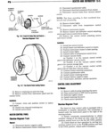
 Next
Next
13 6 HEATER AHD IIEFRDSTER VI DRIITRUL DARLE REPLACEMENT HEATER CURE DJ Ilnrhla GJ Modal lt D e e b e m d e The heater housing haehhhh hhht be 1 I10V d to NOTE The control cabks are retained on the back gam access to the heater Corgi side of the instrument panel by plastic tabs To dis engage the cables from the instrument panel press mma lhgplaagtiv mlb WOFULFT and Pulllml the 1l7l 1 Drain approximately two quarts of coolant from the radiator 2 Remove cable from instrument panel 2 Disconnect battery cables and remove battery 3 Remove cable to damper door 3 Remove battery box 4 Route replacement cable through hole in in 4 Disconnect heater hoses strument panel 5 Disconnect damper door control cables 5 Connectcable to doorand housing 6 Disconnect blower motor wire harness at 6 Install cable to damper door A switch and ground wire at instrument panel 7 Adjust cable and check operation 7 Remove glove box attaching screws and remove glove box 8 Disconnect water drain hose and defroster hose cm YI n rl mck bl 9 Disconnect heater to air deflector duct at isconnect attery negative ca e heater housing g m V i lr r rie t clusterblietalnlng s l W5 10 Remove nuts from heater housing studs in en isconnect spee ometer ca e gine compartment 4 Disconnect electrical connectors from cluster 11 Remove heater housing assemhlv r 5l Disconnect vacuum hoses from vacuum control 12 Remove heater core from heater housing switc NOTE Tag hoses according to their numbered loca lnmlmhn nymfgr gage 0fq eSem y 1 Install heater core in housing 2 Position heater core housing and install attach 6 Remove cluster lights ing Huts 7 Disconnect cable from temperature control 3 Connect water drain hose and defroster hose lever 4 Connect heater to air deflector duct at heater S Remove instrument cluster l 0 5l E 9 Disconnect cable from temperature control 5 Position glove box and installhattachmg screw lever 6 Connect blower motor wire arness at switc 10 Disconnect cable from blend air door and Ewund Wire at instrument Pa l 11 Connect cable to blend air door 7 Connect and adjust damper door control cables 12 Route cable through dash panel and connect to 8 Connect heater hoses temperature control lever 9 Install battery box 13 Position instrument cluster in dash opening 10 Install battery and connect battery cables 14 Install cluster lights 11 Replacecoolant 15 Connect cable to temperature control lever 12 Check heater operation 16 Connect vacuum hoses a Number 1 on the vacuum control switch goes to the defroster vacuum motor ch mk w H r Tr k b Number 3 on the vacuum control switch Mn I goes to the vacuum storage tank we c Number 4 on the vacuum control switch 1 Drain approximately two quarts of coolant goes to the air inlet door vacuum motor from radiator 17 Connect cluster electrical connectors 2 Disconnect temperature control cable from 18 Connect speedometer cable blend air door 19 Install cluster retaining screws 3 Disconnect heater hoses at heater core 20 Connect battery negative cable 4 Disconnect blower motor resistor wires 21 Check heater defroster and fan operation 5 Remove heater core housing to dash panel 22 Adjust cable attaching nuts 23 Check cable operation 6 Remove heater core housing assembly