Ford Parts Wiki | GM Parts Wiki
Home | Search | Browse | Marketplace | Messages | FAQ | Guest
|
Technical Service Manual January 1975 |
|
Prev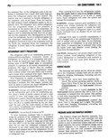
 Next
Next
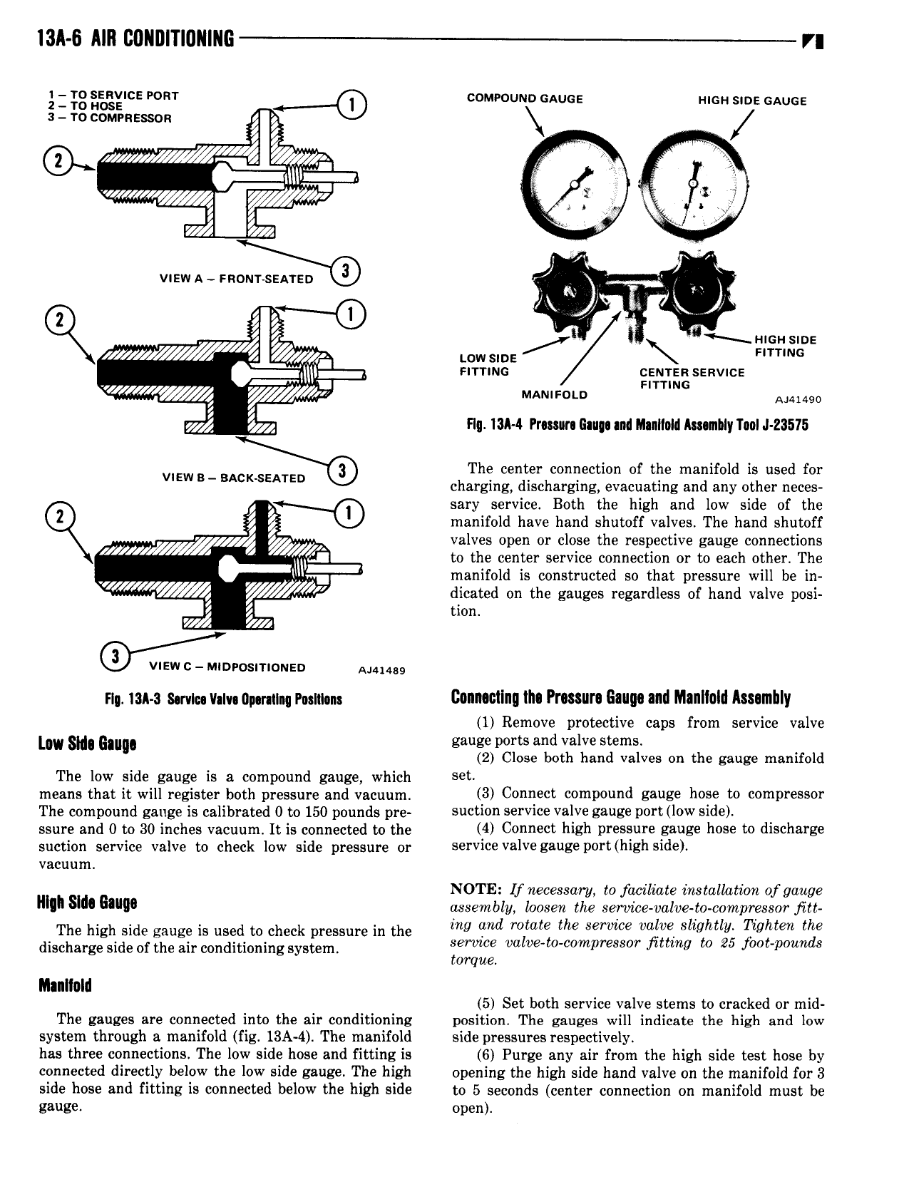
l3A 6 AIR C0ll I l l0llIIlG r 5 gg aegx nce mar comrouun muse mon sane sauce s ro commesson j j e m g il wW Q3 WA h v ewA e J l J l i l srancusnoe 2 J ww sine F u errrmc ceuren senvnce errrmc MANIFOLD Alum I Flq 13A 4 Prmura lau and Ilnlloll Ammlly T 0I J 23575 VIEwB The center connection of the manifold is used for charging discharging evacuating and any other neces I W saryl service Both the high and low side of the Iz manifold have hand shutoff valves The hand shutoff z y valves open or close the respective gauge connections 4 to the center service connection or to each other The q V l v manifold is constructed so that pressure will be in dicated on the gauges regardless of hand valve posi 4 t wd h n osmone Am ng ian mm v lv upminq mlum Conmllng lln Prcssun Gauge and Manllold Ammlily 1 Remove protective caps from service valve my gm glu gauge ports and valve stems 2 Close both hand valves on the gauge manifold The low side gauge is a compound gauge which set means that it will register both pressure and vacuum 3 Connect compound gauge hose to compressor The compound gauge is calibrated 0 to 150 pounds pre suction service valve gauge port low side ssure and 0 to 30 inches vacuum It is connected to the 4 Connect high DFBSBUFE Emile hose W discharge suction service valve to check low side pressure or service valve gauge port high side vacuum NOTE If necessary to faciliate installaticm of gauge muh su Q assembly loosen the service valve t0 compressor fitt The ns side gauge is used to check pressure in the me W Mme the ww vale Sh l hvlfen me discharge side of the air conditioning system iwmce val e t mpr SS T jim to 25 f t p d8 orque lllanllalnl 5 Set both service valve stems to cracked or mid The gauges are connected into the air conditioning position The gauges will indicate the high and low system through a manifold fig 13A 4 The manifold side pressures respectively has three connections The low side hose and fitting is 6 Purge any air from the high side test hose by connected directly below the low side gauge The high opening the high side hand valve on the manifold for 3 side hose and fitting 15 connected below the high side to 5 seconds center connection on manifold must be ghuge open