Ford Parts Wiki | GM Parts Wiki
Home | Search | Browse | Marketplace | Messages | FAQ | Guest
|
Technical Service Manual January 1975 |
|
Prev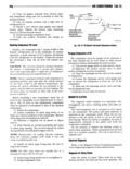
 Next
Next
13A 16 MH CUIIDITIIJIIING VI clutch coil must be mounted properly using the special 6 From underside of vehicle disconnect capscrews which position the field coil to the compres receiver dryer to evaporator hose st receiver dryer sor 7 Remove condenser and receiver dryer assem A worn pulley bearing can be detected by the bly roughness felt when spinning the pulley Do not 8 Remove receiver dryer from condenser if attempt to replace the bearing necessary A new clutch may emit a short squeal when in itially engaged After a few cycles of operation the Immmlnn noise will disappear 1 If removed install receiver dryertocondenser 2 Pl d t d t v Nmr Z Z1vZT Z tJP i ZZ Li LZiv F 1 Remove compressor belts 3 Install condenser attaching screws 2 Energize the clutch or use a spanner wrench to 4 Connect pressure line at condenser hold the clutch plate while removing the clutch to 5 Install radiator andfan shroud shaft attaching bolt and washer 6 Fill radiator 3 Install a 5 8 11 standard thread bolt in the 7 Evacuate leak test and charge the system threaded center of the clutch plate 4 Tighten bolt and pull clutch from the shaft EVAPUMTUR Imusma ASSEMBLY CAUTION Do not pry on clutch to remove mmwal 5 Remove capscrews which retain the magnetic ll Di l S SySi m 4 I coil and disconnect coil wire Remove coil EISCDHHBBE mlet suciasn line at compressor isuonnec receiver ryer to evaporator ose tth u k d n t l f 13A 16 cum msmmnm 4 Remove hose clamps and dash grommet retain 1 Install magnetic coil with the four special ng su eWS capscrews provided with the replacement unit These capscrews are used to ensure the coil is positioned pro perly on the compressor 2 Tighten capscrews to 7 to 10 foot pounds tor que 3 Align clutch assembly with key and install clutch on shaft RECEIVER nnvzm 4 Install clutch to shaft attaching bolt and tigh r A T0 EVAPORATOR ten to 20 fo0t pounds torque Connect clutch coil wire H E and energize clutch to hold unit when tightening 5 Install compressor belt s and adjust belt ten sion to specifications E 6 wg CUNDEIISEII MID RECEIVER DRYER ISSEMBLY t im Removal Qt 1 Discharge refrigerant from system ouicx NOTE Discharge system slowly to prevent loss of g 52rx I 6 mm pressor ml K 2 Drain radiator 3 Remove fan shroud and radiator mgm FRONT 4 Disconnect pressurelineatcondenser FENDER V 5 Remove four condenser attaching screws and tilt bottom of condenser toward engine mm NOTE Plug all open connections to prevent entry of rim and moisture Fl 13A lh 0i I k l wln l G wIm