Ford Parts Wiki | GM Parts Wiki
Home | Search | Browse | Marketplace | Messages | FAQ | Guest
|
Technical Service Manual January 1975 |
|
Prev
 Next
Next
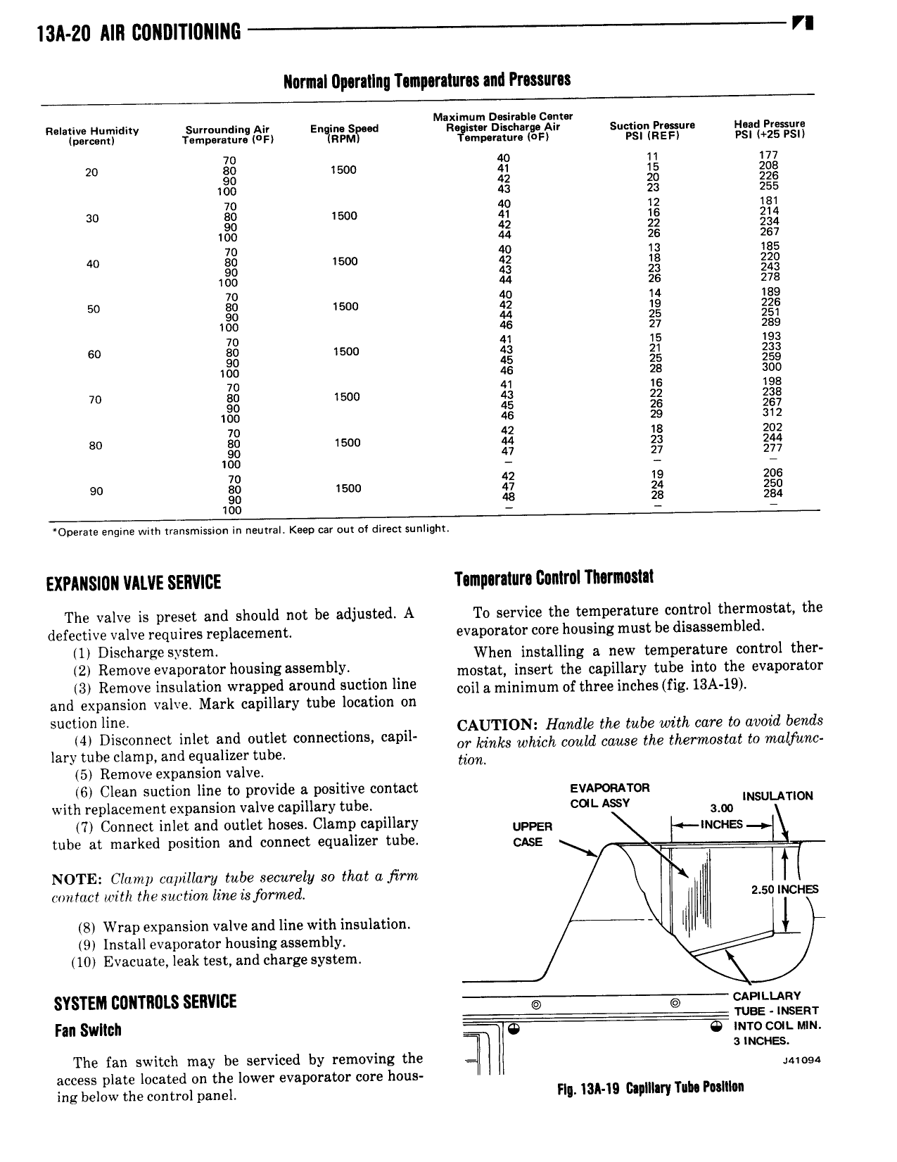
13ll 20 AIII CDIIDITIUIIIIIG VI llerml Uperallnq Temperatures and Pressures Relative Humidity Surrounding Air En im S d M tTr i i ii 2 c ii Suction Pr ssur H ad Prosura percent Temperature Fl 1RPMv m r tur 0F PSI REF PSI 25 PSI 7 20 83 rm ii 1 3 90 42 20 226 100 43 23 255 70 40 12 18i 30 B0 I 500 41 16 21 4 90 42 22 234 l00 44 26 267 70 40 B0 1500 gg 90 43 23 243 1 00 44 26 278 70 40 14 189 50 80 1500 42 19 226 90 44 25 251 100 46 27 289 70 41 15 I93 60 E0 1500 43 21 233 90 45 25 259 100 46 28 300 70 41 IS 198 70 B0 1500 43 22 238 90 45 26 267 100 46 29 312 70 42 18 202 80 80 1500 44 23 244 90 47 27 277 100 70 42 19 206 90 80 1500 47 24 250 90 48 25 284 100 Opersrs engine with transmission in neutral Keep car our at direct sunlight EXPANSIDN VALVE SERVICE Temperature Dunlrel Tliermosm The valve is preset and should not be adjusted A To service the temperature control thermostat the defective valve requires replacement evaporator core housing must be disassembled lll Dlschalge SYsl When installing a new temperature control ther 2 R ap l h 5mg blY mostat insert the capillary tube into the evaporator 13 Remove ll1S 1l81ZlOIl wrapped 8l 0l1I Id SLICEIOI1 llIlE coil a minimum of three inches fig l3A 19 r and expansion valve Mark capillary tube location on s g I d I t 1 CAUTION Heade the tube wan we to mia new Ml lsconnect m et all out et comwc mm cam or kinks which could cause the thermostat to malfimc lary tube clamp and equalizer tube mm 5 Remove expansion valve 6 Clean suction line to provide a positive contact Evapqwrgg with replacement expansion valve capillary tube CUL ASSY lm u T N 7 Connect inlet and outlet hoses Clamp capillary UPPER INCHES tube at marked position and connect equalizer tube CASE NOTE Clamp capillary tube securely so that afirm T mm tact with the suction line Lsforraed 2 5B INCHES 8 Wrap expansion valve and line with insulation 9 Install evaporator housing assembly 10 Evacuate leak test and charge system SYSTEM DDIITRIJLS SERVICE CAPILLARV TUE INSERT Fill Sllllllill Q imo con mn V 3 INCHES The fan switch may be serviced by removing the umu access plate located on the lower evaporator core hous ing below the control panel H 13A ID Capillary Tube Peslllim